
Page 225 - APPLIED PROCESS DESIGN FOR CHEMICAL AND PETROCHEMICAL PLANTS, Volume 1, 3rd Edition
P. 225
Pumping of Liquids i 97
fixed condition of suction lift, and relates speed, head
and capacity. This index is a valuable guide in establishing
the maximum suction lifts and minimum suction heads to
avoid cavitation of the impeller with resultant unstable
hydraulic performance and physical damage. For a given
set of conditions on the suction and discharge of a pump,
a slow rotative speed will operate safer at a higher suction
lift than a pump of higher rotative speed.
eo 8 Rotative Speed
The rotative speed of a pump is dependent upon the
impeller characteristics, type fluid, NPSH available and
so other factors for its final determination. The most direct
method is by reference to manufacturer’s performance
5o w
curves. When a seemingly reasonable selection has been
made, the effect of this selected speed on the factors such
as NPSM required, suction head or lift, fluid erosion and
corrosion, etc., must be evaluated. For many systems these
factors are of no concern or consequence.
Normal electric motor speeds run from the standard
induction speeds for direct connection of 3600, 1800 and
1200 rpm to the Power speed standards of the synchro-
nous motors, and then to the somewhat arbitrary speeds
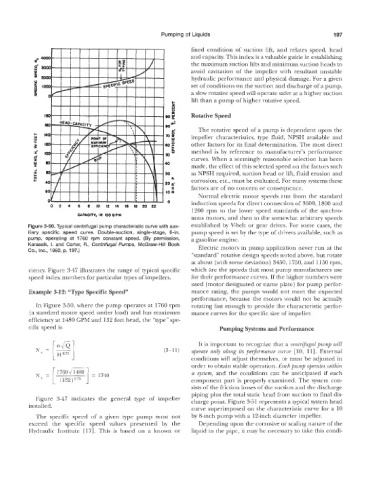
Figure 3-50. Typical centrifugal pump characteristic curve with aux- established by V-belt or gear drives. For some cases, the
iiiary specific speed c:uwe. Double-suction, single-stage, 6411. pump speed is set by the type of drivers available, such as
pump, operating at 3760 rpm constant speed. (By permission, a gasoline engine.
.1 Centrifugal Pumps, McGraw-Hill Book
Electric motors in pump application never run at the
“standard” rotative design speeds noted above, but rotate
at about (with some deviation) 3450.1750, and 1150 rpm,
ciency. Figure 3-47 illustrates the range of typical specific which are the speeds that most pump manufacturers use
speed index numbeirs for particular types of impellers. for their Performance curves. If the higher numbers were
used (motor designated or name plate) for pump perfor-
mance rating, the pumps would not meet the expected
performance, because tkke motors would not be actually
In Figure 3-50, where the pump operates at 1’760 rpm rotating fast enough to provide the characteristic perfor-
(a standard motor speed under bad) and has maximum mance curves for the specific size of impeller.
efficiency at 1480 GPM and 132 feet head, the “type” spe-
cific speed is Pumping systems and
It is important to recognize that a cent@ugal pump will
(3-11) operate only along its perj>rmance curve [la, 111. External
conditions will adjust themselves, or must be adjusted in
order to obtain stable operation. Each pump operates within
a system, and the conditions can be anticipated if each
component part is properly examined. The system con-
sists of the friction losses of the suction and the discharge
piping plus the total static head from suction to final dis-
Figure 3-47 indicates the general type of impeller charge point. Figure 3-31 represents a typical system head
installed.
curve superimposed on the characteristic curve for a 10
The specific speed of a given type pump must not by 8-inch pump with a 12-inch diameter impeller.
exceed the specific speed values presented by the Depending upon the corrosive or scaling nature of the
Hydraulic Institute [H7]. This is based on a known or liquid in the pipe, it may be necessary to take this condi-