
Page 246 - APPLIED PROCESS DESIGN FOR CHEMICAL AND PETROCHEMICAL PLANTS, Volume 1, 3rd Edition
P. 246
21 8 Applied Process Design for Chemical and Petrochemical Plants
Totally -Enclosed
Dust-Proof Oil-Tight
Roller Main and
Pinion-Shaft Bearings
Double Helical Gears
Solid Forged Steel Deep Stuffing Box
Marine Type Connecting Rods Cylinder-no Gaskets
Under Discharge Pressure Packing Lubrication
Positive Flood Lubrication
Provided by Oil Distributing Flange and Screw
Type Gland-Even
Take-up on Packing
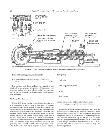
Figure 3-67. Duplex double-acting plunger pump, power driven. (Courtesy Worthington Corp.)
For double acting pumps, single cylinder Horsepower
Q = (two times value for single acting) - 0.0204 dzr t, Hydraulic
GPM (3-48)
For multiple cylinders, multiply the capacities just HHP = Q(actual)H/3960 (3-49)
obtained by the number of cylinders. If the piston rod
does not replace pumping volume as in some arrange- Brake
ments, the last term of the double acting capacity equa-
tion is omitted.
BHP = HHP/e (3-50)
Discharge Flow Patterns
where e represents the total overall efficiency, and is
Figure 3-68 shows the discharge flow patterns for sev- e = em(evol), and e, is the mechanical efficiency.
eral reciprocating power pump actions which are essen-
tially the same for steam pumps. The variations above and
below theoretical mean discharge indicate the magnitude Mechanical efficiencies of steam pumps vary with the
of the pulsations to be expected. Although not shown, the types of pump, stroke and the pressure differential. Some
simplex double acting discharge would follow the action representative values are 55 to 80 percent for piston
of one piston on the duplex double acting curve from 0 pumps with strokes of 3 inches and 24 inches respectively,
to 360". Its variation or pulsing is obvious by inspection, and pressure differential up to 300 psi. For the same
and accumulator bottles would be required to smooth the strokes a plunger design varies from 50 to 78 percent, and
flow. The simplex single acting discharge would be one at over 300 psi differential the efficiencies are 41 to 67
pumping stroke from 0 to 180", then no pumping from percent [9]. Steam required is approximately 120
180" to 360"; and here again the pulse action is obvious. lbs/hour per BHP.