
Page 242 - APPLIED PROCESS DESIGN FOR CHEMICAL AND PETROCHEMICAL PLANTS, Volume 1, 3rd Edition
P. 242
21 4 Applied Process Design for Chemical and Petrochemical Plants
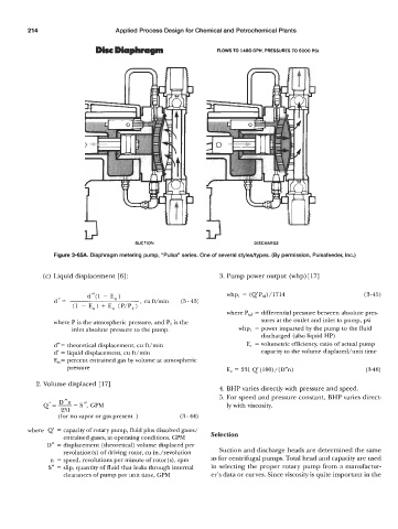
DicrcDiaphny(m FLOWS TO 1480 GPH, PRESSURES TO 5000 PSI
DISCHARGE
Figure 3-MA. Diaphragm metering pump, “Pulsa” series. One of several styleshypes. (By permission, Pulsafeeder, Inc.)
(c) Liquid displacement [6] : 3. Pump power output (whp) [ 171
d”(1 - E, ) whpl = ( Q’Ptd) /1714 (3-45)
d’= , cu ft/min (3- 43)
(1 - E,) + E” (P/P,)
where Ptd = differential pressure between absolute pres-
where P is the.atmospheric pressure, and PI is the sures at the outlet and inlet to pump, psi
inlet absolute pressure to the pump. whpl = power imparted by the pump to the fluid
discharged (also liquid HP)
d“ = theoretical displacement, cu ft/min E, = volumetric efficiency, ratio of actual pump
d’ = liquid displacement, cu ft/min capacity to the volume displaced/unit time
E, = percent entrained gas by volume at atmospheric
pressure E, = 231 Q’(lOO)/(D”n) (3-46)
2. Volume displaced [ 171
4. BHP varies directly with pressure and speed.
5. For speed and pressure constant, BHP varies direct-
Q’=-- ”n S ”, GPM ly with viscosity.
231
(for no vapor or gas present ) (3- 44)
where Q’ = capacity of rotary pump, fluid plus dissolved gases/
entrained gases, at operating conditions, GPM Selection
D” = displacement (theoretical) volume displaced per
revolution(s) of driving rotor, cu in./revolution Suction and discharge heads are determined the same
n = speed, revolutions per minute of rotor(s), rpm as for centrifugal pumps. Total head and capacity are used
S” = slip, quantity of fluid that leaks through internal in selecting the proper rotary pump from a manufactur-
clearances of pump per unit time, GPM er’s data or curves. Since viscosity is quite important in the