
Page 309 - APPLIED PROCESS DESIGN FOR CHEMICAL AND PETROCHEMICAL PLANTS, Volume 1, 3rd Edition
P. 309
Mechanical Separations 281
I
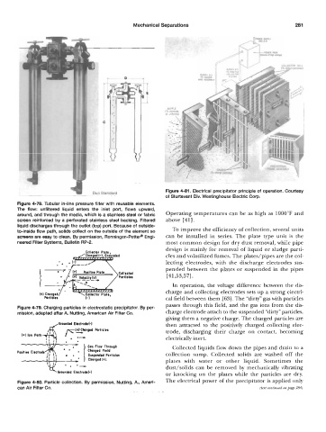
Duo Standard Figure 4-81. Electrical precipitator principle of operation. Courtesy
of Sturtevant Div. Westinghouse Electric Corp.
Figure 4-78. Tubular in-line pressure filter with reusable elements.
The flow: unfiltered liquid enters the inlet port, flows upward,
around, and through the media, which is a stainless steel or fabric Operating temperatures can be as high as 1000°F and
screen reinforced by a perforated stainless steel backing. Filtered above [41].
liquid discharges through the outlet (top) port. Because of outside-
to-inside flow path, solids collect on the outside of the element so To improve the efficiency of collection, several units
screens are easy to clean. By permission, Ronningen-Pettep Engi- can be installed in series. The plate type unit is the
neered Filter Systems, Bulletin RP-2. most common design for dry dust removal, while pipe
design is mainly for removal of liquid or sludge parti-
coII*ctor PIott
cles and volatilized fumes. The plates/pipes are the col-
lecting electrodes, with the discharge electrodes sus-
pended between the plates or suspended in the pipes
[41,53,57].
In operation, the voltage difference between the dis-
charge and collecting electrodes sets up a strong electri-
cal field between them [63]. The “dirty” gas with particles
passes through this field, and the gas ions from the dis-
Figure 4-79. Charging particles in electrostatic precipitator. By per-
mission, adapted after A. Nutting, American Air Filter Co. charge electrode attach to the suspended “dirty” particles,
giving them a negative charge. The charged particles are
,Grounded Ekstrodd-1 then attracted to the positively charged collecting elec-
trode, discharging their charge on contact, becoming
i! ii . e electrically inert.
. Gas Flow Thrauqh Collected liquids flow down the pipes and drain to a
Charged Field
,I !I *-• I SusDendtd Particles collection sump. Collected solids are washed off the
. -* ) Cho;qed(+L plates with water or other liquid. Sometimes the
dust/solids can be removed by mechanically vibrating
or knocking on the plates while the particles are dry.
Figure 4-80. Particle collection. By permission, Nutting, A., Ameri- The electrical power of the precipitator is applied only
can Air Filter Co. (text continued on page 284)