
Page 305 - APPLIED PROCESS DESIGN FOR CHEMICAL AND PETROCHEMICAL PLANTS, Volume 1, 3rd Edition
P. 305
Mechanical Separations 277
some applications, actual testing in the plant using plant
fluid streams can be the most conclusive. This plant test-
ing is not necessary for every situation because the manu-
facturer has large data files to often aid in a good selec-
tion. Generally the ability to collect solids at low flow rates
is greater for the wound filter.
Because the suspended particles are “captured” by dif-
ferent physical mechanisms depending on the particle
size, shape, density, and concentration, all cartridges do
not perform the same. The “capture” may be by (1) direct
interception, (2) sieving, and/or (3) bridging [ 391. (See
Figure 475.) The cartridges from one manufacturer are
generally consistent in performance; however, all car-
tridges from just any manufacturer may not be inter-
changeable in performance.
The micron ratings of a cartridge are intended to indi-
cate the smallest particle that will be retained by the pores
of the filter element. Often a “rough-cut’’ pre-filter is
installed ahead of a final or “polishing” filter in order to
increase the life of the final unit. Unfortunately, the
method for determining the micron rating is not a uni-
versal standard between manufacturers. Thus, one manu-
facturer’s “50 micron” filter may not perform the same as
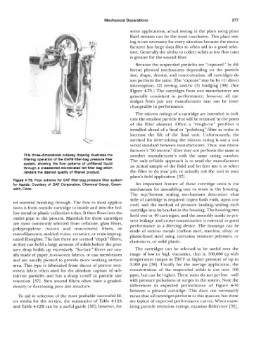
This three-dlmenslonal cutaway drawing Illustrates the another manufacturer’s with the same rating number.
filtering operation of the OAF@ filter-bag pressure filter The only reliable approach is to send the manufacturer
system, showing the flow patterns of unfiltered liquid an actual sample of the fluid and let him test it to select
through a preselected micronrated felt filter bag which
renders the desired quality of filtered product. the filter to do your job, or actually test the unit in your
plant’s field application [37].
Figure 4-73. Flow scheme for GAF filter-bag pressure filter system
for liquids. Courtesy of GAF Corporation, Chemical Group, Green- An important feature of these cartridge units is the
wich, Conn. mechanism for assembling one or more in the housing.
The top/bottom sealing mechanisms determine what
style of cartridge is required (open both ends, open one
ed material breaking through. The flow in most applica- end) and the method of pressure loading/sealing each
tions is from outside cartridge to inside and into the hol-
low metal or plastic collection tubes. It then flows into the cartridge into its bracket in the housing. The housing may
hold one or 40 cartridges, and the assembly inside to pre-
outlet pipe to the process. Materials for these cartridges vent leakage and cross-contamination is essential to good
are most commonly selected from cellulose, glass fibers, performance as a filtering device. The housings can be
polypropylene (woven and non-woven) fibers, or made of various metals (carbon steel, stainless, alloy) or
monofilaments, molded resins, ceramics, or resin-impreg- plastic-lined steel using corrosion resistant polymers, or
nated fiberglass. The last three are termed “depth” filters, elastomers, or solid plastic.
as they can hold a large amount of solids before the pres-
sure drop builds up excessively. “Surface” filters are usu- The cartridges can be selected to be useful over the
ally made of paper, non-woven fabrics, or cast membranes range of low to high viscosities, that is, 100,000 cp with
and are usually pleated to provide more working surface temperature ranges to ’750°F at higher pressure of up to
area. This type is fabricated from sheets of porous non- 3,000 psi [38]. Usually for the average application, the
woven fabric often used for the absolute capture of sub- concentration of the suspended solids is not over 100
micron particles and has a sharp cutoff in particle size ppm, but can be higher. These units do not perforr well
retention [37]. Yarn wound filters often have a graded- with pressure pulsations or surges in the system. Note the
density or decreasing pore size structure. differences in expected performance of Figure 476
between a pleated cartridge. This does not necessarily
To aid in selection of the most probable successful fil- mean that all cartridges perform in this manner, but these
ter media for the service, the summaries of Table 412A are typical of expected performance curves. When exam-
and Table 412B can be a useful guide [38]; however, for ining particle retention ratings, examine Reference [ 391.