
Page 33 - APPLIED PROCESS DESIGN FOR CHEMICAL AND PETROCHEMICAL PLANTS, Volume 1, 3rd Edition
P. 33
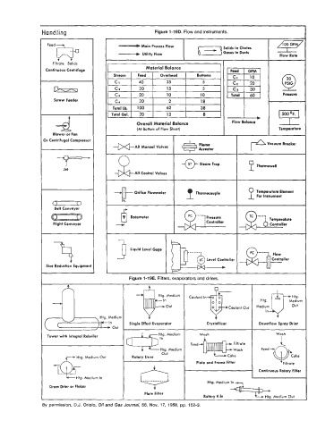
Hand ling                                 Figure 1-19D. Flow and instruments.
                   FeedB                                                            Gases in Ducts       Flow Rate
                                                      Main
                                             - Flow
                                                          Process
                                                                                    Solids in Chutes
                                             ___) Utility Flow
                     Filtrate
                          Solids
                                                                                   I
                  Continuous Centrifuge                Material Balance
                                           Stream   Feed     Overhead  1   Bottoms
                                            Cl    I   40  1    35           5      I T;  @
                                            C,    I   20   I   15     I     5
                     kzzl
                                                                                       Total              Presrun
                     Screw Feeder                                                                    t-G
                      -d                            Overall Material Balance           Flow Balance       500 OF.


                     Blower or Fan                  (At Bottom of Flow Sheet)                            Temporature
                 Or Centrifugal Compressor   *All     Manual Volves   I  ,$   Arrortor              Vacuum Breaker
                                                                           Fkmr
                    -                                                     Thermocouple       P For  Instrument
                     -
                                            --f)- Orifice Flowmeter  1
                I        Jet                       All Control Valves   -@- Steam Trap        P Thermowell


                                                                                                Temporaturr Element


                     Belt Conveyor
                                               T  Rotameter
                     Flight Conveyor        4                                             (J-A   n   Temperature
                                                                                                     Controller
                F,                                Liquid Level Gage                       &)+  j  Controller


                  Size Reduction Equipment

                                                 Figure 1-19E. Filters, evaporators and driers.


                                                    +;rum                        -             I


                                                                                               I
                                                 Single Effect Evoporator     Crystallizer       Downflaw Spray Drier
                                                            Htg. Medium    Wash                         Wash
                   Tower with Integral Reboiler                                                          i
                                                                        Feed
                                                astn Medium
                                                             out
                                                             Htg.
                              Htg. Medium Out     Rotary Drier
                                                                          Plate and Frome Filter          Filtrate
                                                                                                 Continuous Rotary Filter
                     -@ Medium In                                             Htg. Medium In
                             Htg.
                 I   Drum Drier or Flaker              Plate Filter          Rotary Kiln            Htg. Medium Out
                                                          +


                 By permission, B.J.  Oriolo, Oil and Gas Journal, 56, Nov.  17,  1958, pp. 152-3.