Page 34 - APPLIED PROCESS DESIGN FOR CHEMICAL AND PETROCHEMICAL PLANTS, Volume 1, 3rd Edition
P. 34

Process Planning, Scheduling and Flowsheet Design                      21
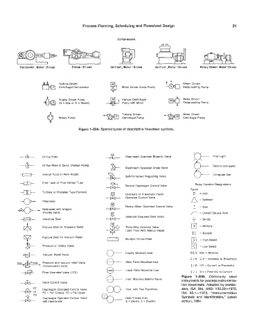

                                                         Compressors


           Horizontal  Motor-Driven   Steam -Driven   Vertical ,Motor -Driven   Vertical, Motor -Driven   Rotary  Blower  Motor-Driven


                             Turbine  Driven                                             Steam  Driven
                             Centrifugal Compressor         Motor Driven  Sump Pump      Reci procati ng P  u m p

                             Engine Driven  Pump            Vertical Centrifugal         Motor  Driven
                             (G = Gas or  D = Diesel)       Pump with  Motor             Reciprocating Pump


                                                            Turbine Driven               Motor  Driven
                             Rotary Pump                    Centrifugal Pump             Centrifugal Pump

                                       Figure 1 -20A. Special types of descriptive flowsheet symbols.


                                                                                              ‘e


           --+I+-    Orifice Plate                  +?+      Diaphragm Operated Butterfly Valve        Pilot  Light
           ---&--    Orifice  Plate in Quick  Change  Fitting   &- Diaphragm Operated Angle Vaive      Data to Computer

           e                                                 Self-Contained  Regulating Valve          Computer  Set
                     Venturi Tube or  Flow Nozzle
           4
                     Pitot Tube or  Pitot Venturi  Tube
                                                             Double Diaphragm Control Valve    Relay Function Designations
                                                                                            Types
                     Turbine or  Propeller Type  Eiement
                                                             Hydraulic or  Pneumatic Piston      =Add
                                                             Operated Control Valve
                     Rotameter                                                                   = Subtract
                                                    2%-                                       -  = Bias
                                                             Rotary Motor Operated Control Valve
                                                                                              +
                     Rotameter  with  Integral
                     Thrott!e Vaive                                                              = Extract  Square Root
                                                             Solenoid Operated Gate Valve
                     Chemical Seal                                                           -   = Divide
                     Rupture Disc for Pressure Relief        Three-way  Solenoid Valve       I_lrl  = Multiply
                                                             Latch Type With  Manual Reset
                                                                                             1:)   = ~ooster
                      Rupture Disc for Vacuum  Relief
                                                             Multiple
                                                     v] Orifice Plate                        I>/  = High Select
                      Pressure or Safety Valve                                               l<r  = Low Select
                                                             Locally  Mounted Instr.        R E V  Rev = Reverse
                     Vacuum  Relief Valve
                                                    @---                                    E/ P  EIP = Potential  to  Pneumatic
                Press.   Pressure aind vacuum relief Valve   Main Panel Mounted lnstr.
                      (Conservation Vent)                                                    I / p  IIP = Current to Pneumatic
                                                             Local Panel Mounted Instr.
                      Float Operated Valve (LCV)                                             E / I  Ell = Potential  io Current
                                                                                        Figure  1 -2OB.  Commonly  used
                                                    a-  Instr. Mounted Behind Panel
                      Wand  Control Valve                                               instruments for process instrumenta-
                                                                                        tion flowsheets. Adapted by permis-
           4:         Diaphragm Operated Control Vaive       Instr. with  Two  Functions   sion,  ISA  Std.  ANSI  V32.20-1975,
                                                                                        ISA  S5.1-1973,  “Instrumentation
                      FC = Fail Closed,  FO = Fail Open
                      Diaphragm Operated Controi Valve       Heat Traced Instr.         Symbols  and  Identification,” Latest
                     with  Handvvheel                        S  = Steam, E = Electric   edition, 1984.
   29   30   31   32   33   34   35   36   37   38   39