
Page 39 - APPLIED PROCESS DESIGN FOR CHEMICAL AND PETROCHEMICAL PLANTS, Volume 1, 3rd Edition
P. 39
26 Applied Process Design for Chemical and Petrochemical Plants
V-NO.
MATL.
SIZE 8 CHECKVALVES
CONN. DESCRIPTION
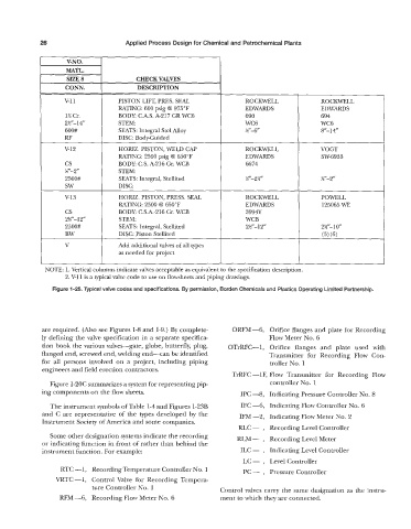
v-11 PISTON LIFT, PRES. SEAL ROCKWELL ROCKWELL
RATING 600 psig @ 975°F EDWARDS EDWARDS
1% Cr. BODY: C.A.S. A-217 GR WC6 690 694
2V-14” STEM: WC6 WC6
600# SEATS: Integral Stel Alloy gr-6” fy-14’’
RF DISC: Body-Guided
v-12 HORIZ. PISTON, WELD CAP ROCKWELL VOGT
RATING 2500 psig 8 650°F EDWARDS SW-6933
cs BODY: C.S. A-216 Gr. WCB 6674
gf-2“ STEM
2500# SEATS: Integral, Stellited r-2gl r-2”
SW DISC:
V-13 HORIZ. PISTON, PRESS. SEAL ROCKWELL POWELL
RATING: 2500 8 650°F EDWARDS 125065 WE
cs BODY C.S.A.-216 Gr. WCB 3994Y 1
2gf-12” STEM: WCB
2500# SEATS: Integral, Stellited 2T-12” 2g-10”
BW DISC: Piston Stellited (5) (6)
V Add additional valves of all types
as needed for project
NOTE: 1. Vertical columns indicate valves acceptable as equivalent to the specification description.
2. V-11 is a typical valve code to use on flowsheets and piping drawings.
Figure 1-25. Typical valve codes and specifications. By permission, Borden Chemicals and Plastics Operating Limited Partnership.
are required. (Also see Figures 1-8 and 1-9.) By complete- ORFM-6, Orifice flanges and plate for Recording
ly defining the valve specification in a separate specifica- Flow Meter No. 6
tion book the various valves-gate, globe, butterfly, plug, OTrRFC--1, Orifice flanges and plate used with
flanged end, screwed end, welding end-can be identified Transmitter for Recording Flow Con-
for all persons involved on a project, including piping troller No. 1
engineers and field erection contractors.
TrRFC -lF, Flow Transmitter for Recording Flow
Figure 1-2OC summarizes a system for representing pip- controller No. 1
ing components on the flow sheets. IPC -8, Indicating Pressure Controller No. 8
The instrument symbols of Table 1-4 and Figures 1-23B IFC -6, Indicating Flow Controller No. 6
and C are representative of the types developed by the IFM -2, Indicating Flow Meter No. 2
Instrument Society of America and some companies.
RLC - , Recording Level Controller
Some other designation systems indicate the recording RLM - , Recording Level Meter
or indicating function in front of rather than behind the
instrument function. For example: ILC - , Indicating Level Controller
LC- , Level Controller
RTC -1, Recording Temperature Controller No. 1 PC - , Pressure Controller
VRTC -1, Control Valve for Recording Tempera-
ture Controller No. 1 Control valves carry the same designation as the instru-
RFM -6, Recording Flow Meter No. 6 ment to which they are connected.