
Page 40 - APPLIED PROCESS DESIGN FOR CHEMICAL AND PETROCHEMICAL PLANTS, Volume 1, 3rd Edition
P. 40
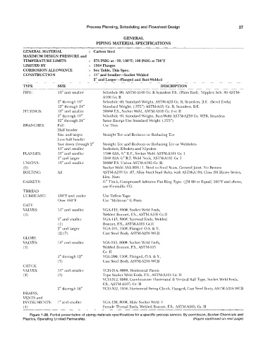
Process Planning, Scheduling and Flowsheet Design                       27


                                                           GENERAL
                                              PIPING MATERIAL SPECIFICATIONS
            GENERAL MaTERwL                :  CarbonSteel
            MAXIMUM DESIGN IPRESSURE and
            TEMPERATURE LIMITS             : 275 PSIG at -20/100”F; 100 PSIG at 750°F
            LIMITED BY                     :  150#Flanges
            CORROSION ALLOINAP\TCE         : See Table, This Spec.
            ~  O   N  S   ~  U  C   ~  ~  ~ :   ~ 1%”’ and Smaller-Socket  Welded
                                             2“ and Larger-Flanged  and Butt-welded
            TYPE            s IZE                                            DESCRIPTION
            PIPE:           1%‘’ and smaller      Schedule 80, ASTM-A106 Gr. B Seamless P.E.  (Plain End). Nipples: Sch. 80 ASTM-
                                                 A106 Gr. B
                            2” through 10“        Schedule 40, Standard Weight, ASTM-A53 Gr. B, Seamless, B.E.  (Bevel Ends)
                            12” through 24”       Standard Weight, (.375”) ASTM-A53, Gr. B, Seamless, B.E.
            FITTINGS:       1%” and smaller       3000# F.S., Socket Weld, ASTM-A105 Gr. I or I1
                            2” through 10”        Schedule 40, Standard Weight, Butt-weld ASTM-A234 Gr. WPB, Seamless
                            12” through 24”       Same Except Use Standard Weight (.3’15”)
            BRANCHES:       Full                  Use Tees
                            Half header
                            Size and larger       Straight Tee and Reducer or Reducing Tee
                            Less half header
                            Size down through 2”   Straight Tee and Reducer or Reducing Tee or Weldolets
                            1%” and smaller       Sockoiets, Elbolets and Nipolets
            FLALVGES:       1%” and smaller       150# ASA, %” R.F., Socket Weld ASTM-A181 Gr. I
                            2” and larger         150# ASA %“ R.F. Weld Neck, ASTM-A181 Gr. I
            UNIONS:         1 %“  and smaller     3000# F.S. Union ASTM-A105 Gr. 11,
            (6)                                   Socket Weld ASA B16.11. Steel to Steel Seats, Ground joint. No Bronze
            BOLTING:        iU1                  ASTM-A193 Gr. B7, Alloy Steel Stud Bolts, with ASTM-Al94, Glass 2H Heavy Series,
                                                  Hex. Nuts
            GASKETS:                              %“ Thick, Compressed Asbestos Flat Ring Type. (JM 60 or Equal) 500°F and above,
                                                  use Flexitallic CG.
            TMRE
            LUBRICANT:      450°F and under       Use Teflon Tape
                            Over 450°F            Use “Molycote”  G Paste
            GATE
            VAWES:          l!4“ and smaller     VGA-112, 800#, Socket Weld Ends,
            (4)                                   Welded Bonnet, F.S., ASTM-A105 GrJI
                            %”  and smaller      VGA-113,800#, Screwed Ends, Welded
                            (1)                   Bonnet, F.S., ASTM-A105 Gr.11
                            2”  and larger       VGA-101, 150#, Flanged OS. & I!,
                            (2) (7)               Cast Steel Body, ASTM-AZ16 WCB
            GLOBE
            VPLL’VES:       1%” and smaller      VGL-215, 800#, Socket Weld Ends,
            (4)                                  Welded Bonnet, F.S., ASTM-105
                                                  Gr. I1
                            2” through 12”       VGL200, 150#, Flanged, OS. & Y3
                            (7)                   Cast Steel Body, ASTM-A216 WCB
            CHECK
            VALVES:         1V and smaller       VCH-314, 800#, Horizontal Piston
            (4)             (3)                   Trpe Socket Weld Ends, F.S., ASTM-A105 Cr. 11
                                                 VCH-312, 800#, Combination Horizontal & Vertical Ball Type, Socket Weld Ends,
                                                  F.S., ASTM-A105, Gr. 11
                            2“ through 16”       VCH-302,150#, Horizontal Swing Check, Flanged, Cast Steel Body, ASTM-A216 WCB
            DRAINS,
            VENTS and
            INSTRUMENTS:    1” and smaller       VGA-120, 800#, Male Socket Weld  X
            (4)                                   Female Thread Ends, Welded Bonnet, F.S., ASTM-A105, Gr. 11
               Figure 11-26. Partial presentation of piping materials specifications for a specific process service. By permission,  orden Chemicals and
            Plastics, Operating Limited Partnership.                                        (Figure continued on next page)