Page 275 - Applied Process Design For Chemical And Petrochemical Plants Volume II
P. 275

264                       Applied Process Design for Chemical and Petrochemical Plants


                                                            n = Q/[4  d2 (h - hd)0.5]                    (9 -  I)

                                                            Q= 5.10 (n) (a)  (h - h,,)O-i                (9 -  2)

                                                            Q= K  (11)  (a)  (h -                        (9 -  3)
                                                            This  is  considered  the  basis  design  for  the  distributor
                                                             [131]. K = 0.16 for average. The hole punch direction has
                                                            a  strong  influence  on  the value  of  K.  = 0.6 if  holes are
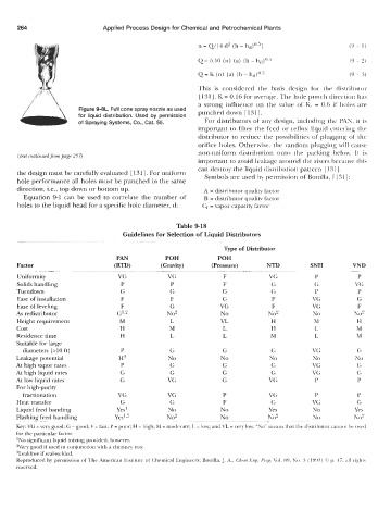
                         Figure 9-8L. Full cone spray nozzle as used   punched down  [ 1311.
                         for  liquid distribution. Used by permission
                         of Spraying Systems, Co., Cat. 55.   For distributors of  any design, including the PAN, it  is
                                                            important to filter the feed or reflux liquid entering the
                                                            distributor  to reduce  the  possibilities of plugging  of  the
                                                            orifice holes. Otherwise, the random  plugging will  cause
      (text continuedjirom page 257)                        non-uniform  distribution  onto  the  packing  below.  It  is
                                                            important to avoid leakage around the risers because this
                                                            can destroy the liquid distribution pattern  [ 1311.
      the design must be carefully evaluated [ 1311. For uniform
      hole performance all holes must be punched in the same   Symbols are used by permission of Bonilla, [ 131 1 :
      direction, i.e., top down or bottom up.                 A = distributor quality Factor
        Equation  9-1  can  be  used  to  correlate the  number of   B  = distributor quality factor
      holes to the liquid head for a specific hole diameter, d:   Cf- = vapor capacity factor


                                                      Table 9-18
                                      Guidelines for Selection of Liquid Distributors
                                       ~~              ~~~            ~~               ~~
                                                                    Type of Distributor
                                    PAN           POH             POH
      Factor                       (RTD)         (Gravity)      (Pressure)       NTD          SNH         VND
                                    __                                                      -                -
      Uniformity                    VG             VG               F            VG            P            P
      Solids handling                P              P               F             G            G           VG
      Turndown                       G              G              G              G            P            P
      Ease of installation           F              F              G              F           VG            G
      Ease of leveling               F              G              VG             F           VG            F
      As  redistributor             GI,*           No2             No            No2          No           No*
      Height requirement             M              L              VL             H            M           H
      cost                           H              M               L             H            L           M
      Residence time                 H              L               L             M            L           M
      Suitable for large
        diameters (>lo ft)           P              G              G              G           VG            G
      Leakage potential              H3            No              No            No           NO           No
      At high vapor rates            P              G              G              G           VG            G
      At high liquid rates           G              G              G              G           VG            G
      At low liquid rates            G             VG              G             VG            P            P
      For high-purity
        fractionation               VG             VG               P            VG            P            P
      Heat transfer                  G              G               F             G           VG           G
      Liquid feed handing           Yes’           No              No            Yes          No           Yes
                                   Yes’,*          No*             No            No*          No           No2
                     ~
      Flashing feed handling  ~~~~
      ~                                                           --            ~~              ~-
      Key  VG = very good, G = good, F = fair, P = poor, H = high, M  = moderate, L = low, and VL = Iery low  “ho” mean\ that rhc  distributor  cannot Ilr  (I\(  d
      for the particular factor
      ‘No significant liquid mixing prowded, however
      Wery good if used in conjunction with a chimnry tray
      ?Leakfree if seal-welded
      Reproduced by  perniisw)n of The American  Inmute of Lhemical  Engineen, Bonilla, J  A, Chrm bng  Pry Vol  89, ho 3 (199s)  0 p  17  nll iiql~t\
      reserved
   270   271   272   273   274   275   276   277   278   279   280