Page 272 - Applied Process Design For Chemical And Petrochemical Plants Volume II
P. 272

T
              i                                             Figure 9-8E. Trough liquid distributor.  Used by permission of  U.S.
                                                            Stoneware Co. (now, Norton Chemical Process Products Corp.).


                                Width   No  of   Flow
               Plate  Overoll  Overall
                                  of
         ‘Er   !:;   !:,,   !;,;   Lugs  Weirs   Per   Ap~perpx.
                                 II D II   Minute)  We’gh’.
          24“’   20”   23”   5%”   3”   8    16   55
          30“   2v   29    5%”    3”   18   36    70
          36’   30”   35“   51%’’   3”   18   36   120
          42”   35,‘   41 ’   5%”   3”   36   72   150
          48”   40“   4w    5w    3”   40    80   190
          60”   50”   58”   6’    $3   48    96   270
                                                            Figure 9-8F. Typical design inlet liquid distributor  using holes (ori-
                                                            fices) on underside of distribution pipes. Note: Number of side pipes
                                                            adjusted to provide uniform entry per square foot  of tower  cross-
                                                            section area. Holes at wall should be spaced on same basis.

                                                                            This  distributor  is  widely  used for
               Koch/Sulzer”                                               structured  packing  applications in
                                                                          medium-to-large-diameter  col-
                                                                          umns. The header above the lateral
                                                                          arrangement  provides  for  cost-
                                                                          effective sectionalized designs with-
                                                                          out the  need for  gaskets. Elevated
                                                                          holes in both the header and laterals
                                                                          provide superb fouling resist0nce.h
                                                                          a resultof multipledrip points‘[MDP).
                                                                          a curtain of liquid falls perpendicular
                                                                          to the top of the packing.
                                                                            In a typical design, the header box
                                                                          may have holes in the floor  or, for
                                                                          fouling services, holes  in  metering
                                                                          boxes  that  are  welded  inside the
                                                                          header The header is leveled inde-
                                                                          pendently by lugs attached to the
                                                                          laterals  Laterals  have  holes
                                                                          punched in the sides above the floor
                                                                          of  the  lateral. The  MDP  baffle  ar-
                                                                          rangement directs  the  liquid onto
                                                                          the  packing with  a  typical  lateral
                                                                          hole  densiw  of  10  points/ftz Turn-
                                                                          down capabilities. typically 2.5:l.  A
                                                                          two-stage design can be provided
                                                                          for higher turndown requirements.
                                                                            Overall  distributor  height  is  ap-
                                                                           proximately  24‘:  The  distributor  is
                                                                           leveled from a supporting grid.
                                                                          which normallyrestson thetopofthe
                                                                           packed bed. The vessel manwoy is
                                                                           usually  located  at  or  above  the
                                                                           header elevation.
                                                                          *US Patent: 4,816.191
                                                                           Canadian Patent 1.261.249
                                                                           “See  note
                                                             NOTE “SULZER”  is the registered trademark of Sulzer Brothers Lid, Winterthur
                                                                 Swrtrerland Koch EnaineerinaCornnanv lnc istheexclime licensee
                                                                 CanadoandMexico
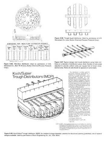
      Figure 9-8G. Koch/Sulzet@ trough distributor (MDP), for medium to large diameter columns for structured packing (patented), one of several
      designs available. Used by permission of Koch Engineering Co.,  Inc., Bull. KS-6.
   267   268   269   270   271   272   273   274   275   276   277