
Page 277 - Applied Process Design For Chemical And Petrochemical Plants Volume II
P. 277
266 Applied Process Design for Chemical and Petrochemical Plants
2. For high purity hydrocarbon fractionation, the num- Uniform distrihrition is essential for- cf'ficiciit use antl
ber of drip points recommended for good irrigation performance of the packirig. 'Hie distribution of drip
is 10-20 drip points/ft'. Increasing the number of points on to the packing sh oul tl cii su re t h e same amouii t
drip points much beyond 20 may not help improve of liquid wettiug of tlie picking for each square foot of
the packing performance. Table 9-19 suggests the tower cross-sectional area. The area near the ~2.all must
approximate number of useful drip points/ft2 for var- also receive its same uniform share of the liquid by eiisur-
ious sizes of random packing. Experience and design irig the same drip points per square foot right out to the
judgment may indicate more or less should be used. vessel wall, i.e., to i\ithin one pitch of the orificy holes
From Table 9-19 Bonilla points out that at the lower from the trough or PAN distributor. Kotiilla I 131 1 siiggests
liquid rates into the distributor a larger number of the following rule of thuml) for distributor design: The
holes are required to effectively wet the packing due outer 10% of the surhce area of the tower cross section
to the lower spreading rates from the lower flows. should have 10% of the total liquid rate; this mtwis 10%
3. Minimum recommended hole diameters [ 1311- of the uniform number of holes. For some situations a sep-
(a) Carbon steel system: %-in. (use filter on entering arate liquid line from a poiiit on tlie distributor over to a
liquid) void layout area may be tieccssary to motv liquid to that
(b) Stainless steel: %in. (experience suggests %,,-in. location. Despite earlier thinking, Bonilla [ 13 I] cmplia-
minimum) (use filter on entering liquid) sizes that the vessel \\.all should receive tlie mile liqiiitl
4. Recommended [131] rule of thumb to avoid liquid unit quantity as the rest of thr packing. Thc general per-
entrainment from the entering liquid by the vapor formance on separation I IETP for poor liquid flow in the
out of the tower: Limit the vapor capacity factor Cf to wall area of the packing is lower compared to the other
about 0.4 ft/sec, regions of the column cross section.
For flashing feeds entering between packed sections it
where Cf = V [(p,)/(pl, - pV)l0.', (9 - 4)
is best to enter on a chimney type tray, alloiviiig the liquid
A value of Cf greater than 0.8 ft/sec in the distributor to mix, and then allow this to flow onto a NTD or PDH
openings is likely to flood the distributor, or result in style tray.
heavy entrainment. For orifice trays a rriiriiiririiii level of 2 in. of liquid
should be held on the tray. This varies ivith the size and
Table 9-19
Suggested Number of Drip Points/Ft2 for Random
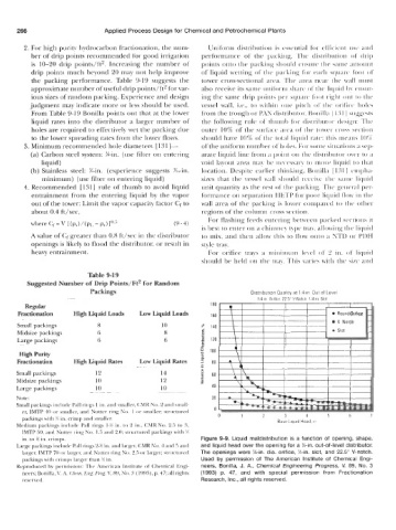
Packings Distribution Quality at 1 4 in Out of Level
~~~~ ~~~~ 114 in Oiifice 22 5" V-Notch 1/4 in Slot
~~ ~~~~ ~ ~~ ~~~~~~~~ ~~
Regular 180
Fractionation High Liquid Loads Low Liquid Loads 160
~ ~~ ~~~ ~ ~~~~ ~~ ~ ~~ ~ ~~ ~~~~~
Small packings 8 10 S- 140
Midsize packings 6 8 i
E!
Large packings 6 6 - 120
~~~ ~~~~~~~ ~~~~~ ~~ ~~ ~ ~~~~~~ ~ ~ ~~ ~
High Purity P 100
Fractionation High Liquid Rates Low Liquid Rates 1 80
U
- -
~~
~~ ~ e
Small packings 12 14 e 60
2
Midsize packings 10 12 s
Large packings 10 10 40
.___
~ ~~~~~~~~~ ~~ ~~~~ ~~~ . ~ ~
Note: 20
Small packings include Pall rings I in. arid smaller, (MR No. 2 antl srnall-
er, IMTP 40 or smaller, and Nutter ring No. 1 or smaller; structured 0
3
4
packings with !4 in. crimp and smaller. 0 1 2 6dse Liquid Head in 5 6 1
Medium parkings include Pall rings 1-W in. to 2 in., CMR No. 2.5 to 3,
IMTP 50, and Nutter ring No. 1.5 and 2.0: structured packings with Y3
in. to W in. crimps. Figure 9-9. Liquid maldistribution is a function of opening, shape,
Large packings include Pall rings 2-% in. and larger, CMR No. 4 and 5 and and liquid head over the opening for a %-in. out-of-level distributor.
larger, IMTP 70 or larger, and Nutter ring No. 2.5 or larger; structured The openings were %-in. dia. orifice, %in. slot, and 22.5" V-notch.
packings with crimps IaIger than W in. Used by permission of The American Institute of Chemical Engi-
Reproduced by permission: Thr American Institute of Chemical Engi- neers, Bonilla, J. A., Chemical Engineering Progress, V. 89, No. 3
neers; Bonilla, 1'. 4. Chrm. Lng. I'rog, V. 89, No. ?I (lYY3), p. 47; a11 rights (1993) p. 47, and with special permission from Fractionation
rrservrd. Research, Inc., all rights reserved.