
Page 278 - Applied Process Design For Chemical And Petrochemical Plants Volume II
P. 278
Packed Towers 267
shape of the drain holes. Figure 9-9 illustrates the effects made for self-adjusting levels of liquid, such as V-notches,
of different base liquid heights over the hole and the which will allow for shifting of tower alignment, brick walls,
resulting variation in liquid distribution for a tray or etc. Gas velocities through the tower at the point of leaving
trough that is %in. out of level, comparing the round and the packing and/or through the distributor plate gas risers
slot orifices and the V-notch. should be low to reduce liquid carry-through. This can be
Parting boxes and troughs are so special to the system calculated by using liquid entrainment limitations. From
flows that after the engineer has established these, the ser- limited tests it appears that there is essentially no entrain-
vices of a competent manufacturer should be consulted. ment off a packing until the flooding point is reached.
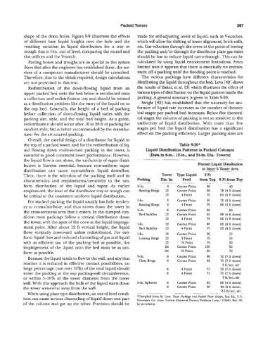
Therefore, due to the detail required, design calculations The various packings have different characteristics for
are not presented in this text. distributing the liquid throughout the bed. Leva [MI shows
Redistribution of the down-flowing liquid from an the results of Baker, et al. [3] which illustrates the effect of
upper packed bed onto the bed below is recollected onto various types of distribution on the liquid pattern inside the
a collection and redistribution tray and should be treated packing. A general summary is giten in Table 9-20.
as a distribution problem like the entry of the liquid on to Strigle [82] has established that the necessity for uni-
the top bed. Generally the height of a bed of packing formity of liquid rate increases as the number of theoret-
before collection of down-flowing liquid varies with the ical stages per packed bed increases. Below five theoreti-
packing size, style, and the total bed height, As a guide, cal stages the column of packing is not so sensitive to the
redistributicn should occur after 10 to 20 ft of packing for uniformity of liquid distribution. With more than five
random st)-le; but is better recommended by the manufac- stages per bed the liquid distribution has a significant
turer for the structured packing. effect on the packing efficiency. Larger packing sizes are
Overall, the careful design of a distributor for liquid in
the top of a packed tower, and for the redistribution of liq- Table 9-20'
uid flowing dow7n multi-section packing in the tower, is Iiquid Distribution Patterns in Packed Columns
essential to good consistent tower performance. However, (Data in 6-in., 12-in., and 24in. Dia. Towers)
the liquid flow is not alone, the uniformity of vapor distri- . . - . . .-
bution is likewise essential, because non-uniform vapor Percent Liquid Distribution
distribution can cause non-uniform liquid downflow. in Inner % Tower Area ..
. .
.
... ..
Then, there is he selection of the packing itself and its Tower TypeLiquid 2 Ft
characteristics and requirements/sensitivity to the uni- Packing Dia.In. _. Feed from Top 8 Ft Erom Top
. .
.
.-
form distribution of the liquid and vapor. As earlier %-In. 6 Center Point 40 40
emphasized, the level of the distributor tray or trough can RaschigRings 12 Center Point 90 78 (4ftdown)
be critica! tc the consistent uniform liquid distribution. 12 4 Point 70 69 (4ftdown)
For stacked packing the liquid usually has little tenden- 1-In. 2 Center Point 95 70 (4 ft down)
cy to crossdis-tribute, and thrw moves down the tower in RaschigRings 2 4 Point 70 60 (4 fi down)
the cross-sectional area that ic enters. In the dumped con- %In. 6 Chter Point 60 50
dition most. packings follow a conical distribution down Berl Saddles 12 Center Point 95 88 (4 ft down)
12
4 Point
70
60 (4 ft down)
the tower, with the apex of the cone at the liquid impinge- I-In. 12 Center Point 85 65 (4ftdown)
ment point. After about 12 ft vertical height, the liquid Berl Saddles 12 4 Point 75 55 (4 ft down)
flows vertically downward unless redistributed. For uni- 1-In. 12 Center Point 90 35
form liquid flow and reduced channeling of ,gas and liquid Lessing Rings 12 4 Point 70 95
with as efficient use of the packing bed as possible, the 12 19 Point 70 90
impingement of the liquid onto the bed must be as uni- 24 Center Point 100 90
form as possible. 24 12 Point 80 70
Because the liquid tends to flow to the 14, and any that K-In. 6 Center Point 90 70 (7 ft down)
reaches it is reduced in effective contact possibilities, no Glass Rings 6 Ccnter Point 83 7.5 (7 ft down)
3 ft/sec, air
large percentage (not over 10%) of the total liquid should 6 4 Point 75 70 (7 fi down)
enter the packing at the top packing-wall circumference, 6 4 Point 73 7.5 (7 rt down)
or wizhin !%lo% of the tower diameter from the tower 3 ft/sec, air
wall. With this approach the bulk of the liquid starts down %In.Spheres 6 Center Point 83 85 (4ft down)
the tower somewhat away frcm &e wall. 6 Center Point 90 90 (4 ft down,
- -
--
,~
..
When using platetype distributors, an out-of-level condi- - .- __ . - . 2.5 ft/sec. air .-
._
.
.
tion can cause serious channeling of liquid down one part *Compiled from M. Leva. Taw PacJiings and Pa& Tm- Ihs+gn, 2nd Ed., L.S.
Stoneware Co. (now, Norton Chemical Process Products Corp.) (1933). kf. 40,
of the column and gas up the other. Provision should be by pelmission.