
Page 287 - Applied Process Design For Chemical And Petrochemical Plants Volume II
P. 287
276 Applied Process Design for Chemical and Petrochemical Plants
OVerVieur
Kunesh [126] presents an overview of the basis for
selecting random packing for a column application. In
first deciding between a trayed tower or a packed one, a
comparative performance design and its mechanical inter-
pretation should be completed, considering pressure
drop, capacity limitations, performance efficiencies
(HETP), material/heat balances for each alternate. For
one example relating to differences in liquid distribution
performance, see Reference 126.
For a packed tower selection, the larger packing size
generally provides the greater capacity, with less pressure
drop, but at the expense of lower efficiency (higher
HETP) than a somewhat smaller size. Some of the ulti-
mate performance depends on the column diameter, the
length devoted to packing, the primary variable deter-
mined to be packing size, with packing type an important
secondary consideration. Obviously, there is a close bal-
ance here, particularly between the various design shapes
(types) of the different manufacturers.
For quite accurate performance data on a specific pack-
ing type/size, consult the respective manufacturers and do
not rely only on the generalization charts of the published
literature. Because these charts are continuously being
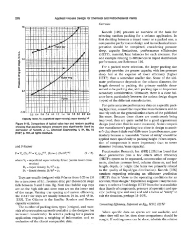
Capacity factor, Fs, (superficial vapor velocity) (vapor density)lE
improved, they are quite useful for a good approximate
Figure 9-19. Comparison of typical valve tray and random packing design (and even final in some instances). Some competi-
showing that packing reduces pressure drop significantly. Used by tive manufacturer’s packing is so close in design to anoth-
permission of Kunesh, J. G., Chemical Engineering, V. 94, No. 18 er’s that there is little real difference in performance, par-
(1 987) p. 101, all rights reserved.
ticularly because a reasonable “factor of safety” should be
applied more specifically to packing height (when separa-
tion of components is more important) than to tower
and F-Factor diameter (volume/mass capacity).
Fractionation Research, Inc. (FRI) [126] has found that
F = V, (Dv)0.5 = V, (P,)O.~, (ft/sec) (Ib/ft3)0.j (9 - 13)
these parameters plus a few others affect efficiency
(HETP) : system to be separated, concentration of compo-
where V, = superficial vapor velocity, ft/sec (across tower cross-
section) nents, absolute pressure level, column diameter, and bed
D, = vapor density, lb/ft3 = pv length, depth, or height (the latter two primarily related
D1 = liquid densit);, Ib/ft3 = p1 to the quality of liquid/gas distribution). Kunesh [126]
cautions regarding selecting an efficiency prediction
Trays are usually designed with F-factor from 0.25 to 2.0 (HETP) that is “close to the operating conditions for an
for a turndown of 8:l. Pressure drop per theoretical stage accurate/final design.” Experience suggests it may be nec-
falls between 3 and 8 mm Hg. Note that bubble cap trays essary to select a final design HETP from the best available
are on the high side and sieve trays are on the lower end data (family of compounds, pressure of operation and spe-
of the range. Varying tray spacing and system efficiency, cific packing type and size) and add a factor of “safety” to
the HETP for trays are usually between 24 in. and 48 in. suit the situation, perhaps 15-30%.
[133]. The Gfactor is the familiar Souders and Brown
capacity equation. Contacting Efficiency, Expressed as Kg, HTU HETP
The number of packing sizes, types (designs), and mate-
rials of construction currently available to the designer has When specific data on system are not available, and
increased considerably. To select a packing for a process often they will not be, then close comparisons should be
application requires a weighing of information and an sought. If nothing more can be done, tabulate the relative
evaluation of the closest comparable data.