
Page 304 - Applied Process Design For Chemical And Petrochemical Plants Volume II
P. 304
Packed Towers 293
0.02 0.04 0.07 0.10 0.2 0.4 0.7 1.0 1.5 2.0 30
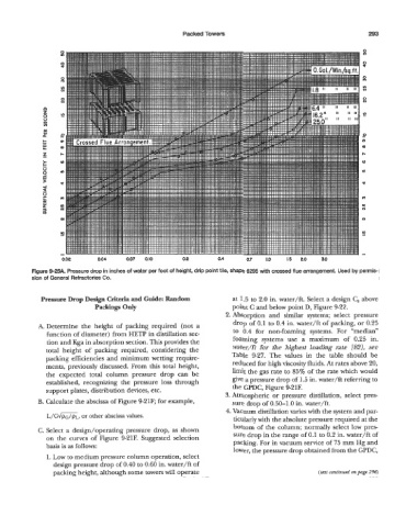
Figure 9-25A. Pressure drop in inches of water per foot of height, drip point tile, shape 6295 with crossed flue arrangement. Used by permis-
sion of General Refractories Co.
Pressure Drop Design Criteria and Guide: Random at 1.5 to 2.0 in. water/ft. Select a design C, above
Packings Only point C and below point D, Figure 9-22.
2. Absorption and similar systems; select pressure
drop of 0.1 to 0.4 in. water/ft of packing, or 0.25
A. Determine the height of packing required (not a
function of diameter) from HETP in distillation sec- to 0.4 for non-foaming systems. For “median”
tion and Kga in absorption section. This provides the foaming systems use a maximum of 0.25 in.
total height of packing required, considering the water/ft for the highest loading rate [82], see
packing efficiencies and minimum wetting require- Table 9-27. The values in the table should be
ments, previously discussed. From this total height, reduced for high viscosity fluids. At rates above 20,
the expected total column pressure drop can be limit the gas rate to 85% of the rate which would
established, recognizing the pressure loss through give a pressure drop of 1.5 in. water/ft referring to
support plates, distribution devices, etc. the GPDC, Figure 9-21F.
3. Atmospheric or pressure distillation, select pres-
B. Calculate the abscissa of Figure 9-21F; for example, sure drop of 0.50-1.0 in. water/ft.
4. Vacuum distillation varies with the system and par-
L/G~L, other abscissa values.
or
ticularly with the absolute pressure required at the
bottom of the column; normally select low pres
C. Select a design/operating pressure drop, as shown sure drop in the range of 0.1 to 0.2 in. water/ft of
on the curves of Figure 9-21F. Suggested selection
basis is as follows: packing. For in vacuum service of 75 mm Hg and
lower, the pressure drop obtained from the GPDC,
1. Low to medium pressure column operation, select
design pressure drop of 0.40 to 0.60 in. water/ft of
packing height, although some towers will operate (lext continued on page 296)