
Page 307 - Applied Process Design For Chemical And Petrochemical Plants Volume II
P. 307
296 Applied Process Design for Chemical and Petrochemical Plants
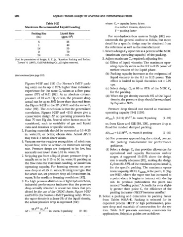
Table 9-27 where C, = capacity factor, ft/sec
Maximum Recommended Liquid Loading o = surface tension, dynes/cm
~ F = packing factor
Packing Size Liquid Rate
(i=) (gpm/ft2) For non-hydrocarbon systems Strigle [82] rec-
-. ommends the general outline to follow, but more
% 25 detail for a specific design may be obtained from
1 40
1% 55 the reference as well as the manufacturer:
2 70 1. Select a design C, vapor rate as a percent of the MOC
3!4 125 (maximum operating capacity) of the packing.
Used by permission of Strigle, R F., Jr., “Random Packing and Packed 2. Adjust maximum Cs required; adjusting for:
Towers” 0 (1987), Gulf Publishing Co., all rights reserved. (a) Effect of liquid viscosity: The maximum oper-
ating capacity varies as the 0.2 to 0.25 power of
surface tension of the liquid phase.
(b) Packing capacity increases as the reciprocal. of
(text continuedpm page 293)
liquid viscosity to the 0.1 to 0.13 power. This
effect is limited to liquid viscosities not < 0.09
Figures 9-21F and 21G (for Norton’s IMTP pack- cps.
ing only) can be up to 20% higher than industrial (c) Select design C, at 80 to 87% of the MOC Cs
experience for the same C, values at a flow para- for the packing.
meter (FP) of 0.01 [82]. At an absolute column (d) When the gas density exceeds 6% of the liquid
pressure of 10 mm Hg or less, the pressure drop density, the pressure drop should be examined
actual can be up to 30% lower than that read from by Equation 9-25.
the Figure 9-21F at the FP of 0.01 and the same C,
value [82]. The conclusion is that the generalized Pressure drop should not exceed at maximum
correlation, Figures 9-21F and -21G always give a operating capacity [941 [1391:
conservative design AP at operating pressures less
than 70 mm Hg abs. Several other factors must be AP,, b (0.019) (F)0.7, in. water/ft packing (9 - 26)
considered, such as variability of gas and liquid or, from Kister and Gill [93, 1391, pressure drop at
rates and densities or specific volumes. flood for random dumped packing:
5. Foaming materials should be operated at 0.1-0.25
in. water/ft, or better, obtain data. Actual AP/ft @flood = 0.115@.7, in. water/ft packing (9 - 20)
may run 2-5 times chart values. (e) For pressures approaching the critical, contact
6. Vacuum service requires recognition of minimum the packing manufacturer for performance
liquid flow; refer to section on minimum wetting guidance.
rate. Pressure drops are designed to be low, but (fl Select a design C, that provides allowances for
normally not lower than 0.10 in. water/ft. operational and capacity fluctuation and/or
7. Stripping gas from a liquid phase; pressure drop is surges. A suggested 15-25% above the design
usually set to be 0.15 to 50 in. water/ft packing at rate is usually adequate [82], making the design
the flow rates for maximum loading, or maximum C, from 80437% of the maximum operational C,
operating capacity. For foaming systems set pres for the specific packing. The maximum opera-
sure drop at 50.25 in. water/ft using inert gas. But tional capacity, MOC, Cs,max, is the point, C (Fig-
for steam use, set pressure drop 50.3 maximum in. ure 422), where the vapor rate has increased to
water/ft for medium foaming conditions [82]. a point where it begins to interact with the liq-
8. For high pressure distillation of light hydrocarbons, uid. In previous publications this point was
industrial performance indicates that the pressure termed “loading point.” Actually for rates slight-
drop actually obtained is about two times that pre- ly greater than point C, the efficiency of the
dicted by the use of the GPDC charts, Figure 9-21F packing increases (HETP becomes smaller).
and 9-21G (for Norton’s IMTP packing only). When D. Select a packing and determine its packing factor
the vapor density is at least 6% of the liquid density, from Tables 9-26A-E. Packing is selected for its
the actual pressure drop is expressed [82] : expected process HETP or Kga performance, pres-
sure drop and materials of construction for the sys-
33 F0.5 (C, )2.4 tem. Table 9-17 presents summary comments for
AP = in. water/ ft packing (9 - 25)
0 applications. Selection guides are as follows: