
Page 311 - Applied Process Design For Chemical And Petrochemical Plants Volume II
P. 311
300 Applied Process Design for Chemical and Petrochemical Plants
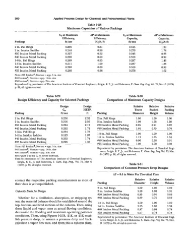
Table 928
Maximum Capacities of Various Packings
- ~ ~
C, at Maximum AP at Maximum Cs at Maximum AP at Maximum
Efficiency, Efficiency, Capacity, Capacity,
Packings ft/sec HZO/ft ft/sec HzO/ft
~ ~ ~
2 in. Pall Rings 0.295 0.81 0.315 1.29
2 in. Intalox Saddles 0.248 0.96 0.279 1.74
#50 Intalox Metal Packing 0.327 0.52 0.345 0.88
#40 Intalox Metal Packing 0.290 0.60 0.310 0.99
I-gin. Pall Rings 0.269 0.95 0.287 1.48
14 in. Intalox Saddles 0.21 1 1.09 0.237 1.88
#40 Intalox Metal Packing 0.290 0.60 0.310 0.99
#25 Intalox Metal Packing 0.260 0.96 0.278 1.62
.. . ~~ ~_
Note: #25 Intalox@, Norton = app. 1-in. size
#40 Intalox", Norton = app. Win. size
#30 Intalox", Norton = app. 2-in. size
Reproduced by permission of The American Institute of Chemical Engineers, Strigle, R. F., Jr. and Rukovena, F. Ch. Eng. hg. Vol. 73, Mar. 0 (1979)
p. 86, all rights reserved.
Table 9-29 Table 9-30
Design Efficiency and Capacity for Selected Packings Comparison of Maximum Capacity Designs
~. ~
Design Design Relative Relative Relative
CS, HETP, TOW- Packed Packing
Packing ft/sec ft Packing Diameter Height Volume
2 in. Pall Rings 0.256 2.32 2 in. Pall Rings 1.00 1.00 1.00
2 in. Intalox Saddles 0.216 2.50 2 in. Intalox Saddles 1.09 1.08 1.28
#50 Intalox Metal Packing 0.284 2.12 #50 Intalox Metal Packing 0.95 0.91 0.82
#40 Intalox Metal Packing 0.252 1.74 #40 Intalox Metal Packing 1.01 0.75 0.76
1-!4in. Pall Rings 0.234 1.78 ~
14 in. Intalox Saddles 0.183 1.87 1-?4in. Pall Rings 1.00 1.00 1 .oo
?+IO Intalox Metal Packing 0.252 1.74 1-W in. Intalox Saddles 1.13 1.05 1.34
#25 Intalox Metal Packing 0.226 1.38 #40 Intalox Metal Packing 0.96 0.98 0.91
#25 Intalox Metal Packing 1.02 0.78 0.80
Note: #25 Intalox", Norton = app. 1-in. size ~. ~
Reproduced by permission: The American Institute of Chemical Engi-
#40 Intalox@, Norton = app. Win. size
#50 Intalox@, Norton = app. 2-in. size neers, Strigle, R. F., Jr., and Rukovena, F., Ch. Eng. Prog. Vol. 73, Mar.
See Figure 9-22 for C, w. tower internals. 0 (1979) p. 86, all rights reserved.
Used by permission of The American Institute of Chemical Engineers,
Strigle, R. F., Jr. andRukovena, F. Chm. Eng. Prog., Vol. 75, Mar. 0
(1979) p. 86, all rights reserved. Table 9-31
Comparison of Constant Pressure Drop Designs
AP = 0.5 in Water Per Therotid Plate
contact the respective packing manufacturers as most of Relative Relative Relative
their data is yet unpublished. Packing Diameter Height Volume
2 in. Pall Rings 1.00 1.00 1.00
Capacity Basis for Design 2 in. Intalox Saddles 1.10 1.08 1.31
#50 Intalox Metal Packing 0.85 0.91 0.66
Whether for a distillation, absorption, or stripping sys- #40 Intalox Metal Packing 0.89 0.75 0.59
tem the material balance should be established around the 1-M in. Pall Rings 1 .oo 1.00 1 .oo
top, bottom, and feed sections of the column. Then, using I-M in. Intalox Saddles 1.13 1.05 1.34
these liquid and vapor rates at actual flowing conditions, #40 Intalox Metal Packing 0.87 0.98 0.74
determine the flooding and maximum operating points or #23 Intalox Metal Packing 0.97 0.78 0.73
conditions. Then, using Figures 9-21B, -21E, or -21F, estab- Reproduced by permission: The American Institute of Chemical Engi-
lish pressure drop, or assume a pressure drop and back- neers, Strigle, R. F., Jr., and Rukovena, F., Chern. Eng. Pmg. Vol. 75, Mar.,
calculate a vapor flow rate, and from this a column diam- 0 (1979) p. 86, all rights reserved.