
Page 31 - Applied Process Design For Chemical And Petrochemical Plants Volume II
P. 31
20 Applied Process Design for Chemical and Petrochemical Plants
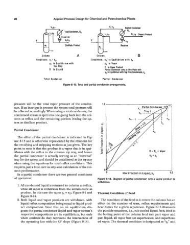
ParHal Condenser
Qc
Product
Distillate Product Receiver
Column A Column B
Conditions : yT = xD Conditions: yD in Equilibrium with xo
yT in Equilibrium with yD is Vapor
Tap Tray D is Vapor Product
D is Liquid Partial Condenser acts as One Plate with
yo in Equilibrium with Top Tray Condensate. ~0
Total Condenser Partial Condenser
Figure 8-13. Total and partial condenser arrangements.
pressure will be the total vapor pressure of the conden-
sate. If an inert gas is present the system total pressure will
be affected accordingly. When using a total condenser, the
condensed stream is split into one going back into the col-
umn as reflux and the remaining portion leaving the sys-
tem as distillate product. s
i
Partial Condenser 0
Q
m
>
c
The effect of the partial condenser is indicated in Fig- .-
ure 8-13 and is otherwise represented by the relations for
the rectifying and stripping sections as just given. The key
point to note is that the product is a vapor that is in equi-
librium with the reflux to the column top tray, and hence D = D, = Vapor
the partial condenser is actually serving as an “external”
tray for the system and should be considered as the top tray
when using the equations for total reflux conditions. This
requires just a little care in stepwise calculation of the col-
umn performance. 1 .o
In a partial condenser there are two general conditions 0 Mol Fraction in Liquid, x,
of operation: Figure 8-14. Diagram of partial condenser; only a vapor product is
withdrawn.
1. All condensed liquid is returned to column as reflux,
while all vapor is withdrawn from the accumulator as
product. In this case the vapor yc = XD; Figure 8-1 and Thermal Condition of Feed
Figure 8-14.
2. Both liquid and vapor products are withdrawn, with The condition of the feed as it enters the column has an
liquid reflux composition being equal to liquid prod- effect on the number of trays, reflux requirements and
uct composition. Note that on an equilibrium dia- heat duties for a given separation. Figure 8-15 illustrates
gram the partial condenser liquid and vapor stream’s the possible situations, i.e., sub-cooled liquid feed, feed at
respective compositions are in equilibrium, but only the boiling point of the column feed tray, part vapor and
when combined do they represent the intersection of part liquid, all vapor but not superheated, and superheat-
the operating line with the 45” slope (Figure 8-14). ed vapor. The thermal condition is designated as “q,” and