
Page 26 - Applied Process Design For Chemical And Petrochemical Plants Volume II
P. 26
Distillation 15
Mol fraction n-hexane in liquid = x3 = 0.786/7.631 = L(m + 1) X(m + 1)i =vm Ymi + BxBi (8-19)
1 .ooo
Operating Line Equation:
Mol fraction in vapor phase at 190°F. Raoult’s Law:
(8 - 20)
yi = pi/= = (pi* xi)/x (for a binary system) (8 - 3)
f7i = (xi Pi)/(xlP~ + x& + ~$3) (for multicomponent Conditions of Operation (usually fixed):
mixtures) (8 - 13)
1. Feed composition, and quantity.
yi= 0.448 (235)/[(0.449) (65) + (0.448) (235) + (0.103) (26)J
= 105.28/[29.185 + 105.28 + 2.6781 = 105.28/[137.143] 2. Reflux Ratio (this may be a part of the initial
= 0.767 unknowns).
3. Thermal condition of feed (at boiling point, all
y2 = 0.449 (65)/137.143 = 0.212 vapor, subcooled liquid).
y3 = 0.103 (26)/137.143 = 0.0195 4. Degree, type or amount of fractionation or separa-
xyi = 0.998 (not rounded) tion, including compositions of overhead or bottoms.
5. Column operating pressure or temperature of con-
Because, Prod = (0.448) (235) + 0.449 (65) + 0.103 (26) densation of overhead (determined by temperature
= 137.14 psia of cooling medium), including type of condensation,
i.e., total or partial.
This is greater than the seIected pressure of 110 psia, 6. Constant molal overflow fiom stage to stage (theo-
therefore, for a binary the results will work out without a retical) for simple ideal systems following Raoult’s
trial-and-error solution. But, for the case of other mixtures Law. More complicated techniques apply for non-
of 3 or more components, the trial-and-error assumption ideal systems.
of the temperature for the vapor pressure will require a
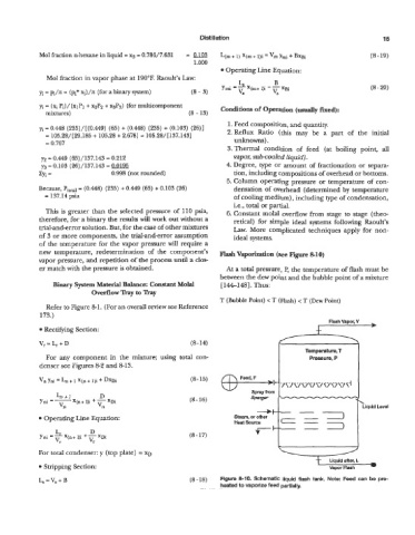
new temperature, redetermination of the component’s Flash Vaporization (see Figure. 8-10)
vapor pressure, and repetition of the process until a clos-
er match with the pressure is obtained. At a total pressure, P, the temperature of flash must be
between the dew point and the bubble point of a mixture
Binary System Material Balance: Constant Molal [ 161481. Thus:
Overflow Tray to Tray
T (Bubble Point) < T (Flash) < T (Dew Point)
Refer to Figure 81. (For an overall review see Reference
173.)
Flash Vapor, V b
Rectifying Section:
Vr=L+D (8-14)
Temperature, T
For any component in the mixture; using total con- Pressure, P
denser see Figures 8-2 and 8-13.
vn hi = + 1 X(n + 1)i + DxDi (8-15)
L+l D
Yni =- X(n+ l)i -t - XDi (8- 16)
vn vll
Operating Line Equation:
(8 - 17)
For total condenser: y (top plate) =‘XD
Stripping Section: Vapor Flash
L, = V, + B (8 -18) Figure 8-10. Schematic liquid flash tank. Note: Feed can be pre-
heated to vaporize feed partially.