
Page 134 - 05. Subyek Teknik Mesin - Automobile Mechanical and Electrical Systems Automotive Technology Vehicle Maintenance and Repair (Vehicle Maintenance Repr Nv2) by Tom Denton
P. 134
2
118 Automobile mechanical and electrical systems
Figure 2.69 Con rod features: 1, front of engine; 2, identifi cation marks; 3, big end cap; 4, oil
spray hole for cylinder wall lubrication
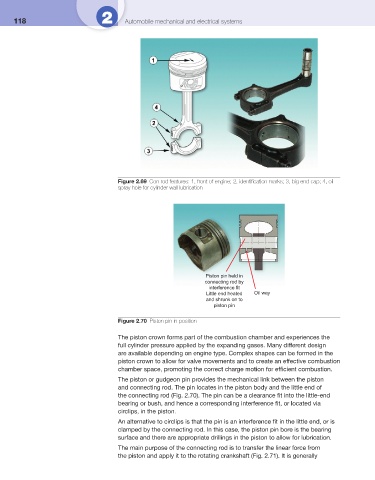
Piston pin held in
connecting rod by
interference fit
Little end heated Oil way
and shrunk on to
piston pin
Figure 2.70 Piston pin in position
The piston crown forms part of the combustion chamber and experiences the
full cylinder pressure applied by the expanding gases. Many different design
are available depending on engine type. Complex shapes can be formed in the
piston crown to allow for valve movements and to create an effective combustion
chamber space, promoting the correct charge motion for effi cient combustion.
The piston or gudgeon pin provides the mechanical link between the piston
and connecting rod. The pin locates in the piston body and the little end of
the connecting rod ( Fig. 2.70 ). The pin can be a clearance fi t into the little-end
bearing or bush, and hence a corresponding interference fi t, or located via
circlips, in the piston.
An alternative to circlips is that the pin is an interference fi t in the little end, or is
clamped by the connecting rod. In this case, the piston pin bore is the bearing
surface and there are appropriate drillings in the piston to allow for lubrication.
The main purpose of the connecting rod is to transfer the linear force from
the piston and apply it to the rotating crankshaft ( Fig. 2.71 ). It is generally