
Page 132 - 05. Subyek Teknik Mesin - Automobile Mechanical and Electrical Systems Automotive Technology Vehicle Maintenance and Repair (Vehicle Maintenance Repr Nv2) by Tom Denton
P. 132
2
116 Automobile mechanical and electrical systems
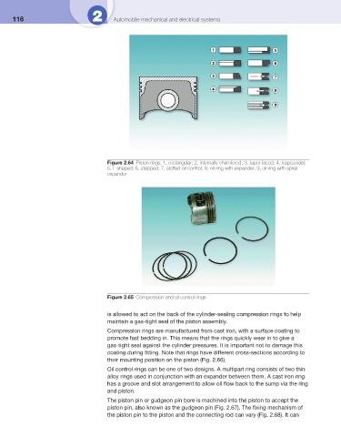
Figure 2.64 Piston rings: 1, rectangular; 2, internally chamfered; 3, taper faced; 4, trapezoidal;
5, L shaped; 6, stepped; 7, slotted oil control; 8, oil ring with expander; 9, oil ring with spiral
expander
Figure 2.65 Compression and oil control rings
is allowed to act on the back of the cylinder-sealing compression rings to help
maintain a gas-tight seal of the piston assembly.
Compression rings are manufactured from cast iron, with a surface coating to
promote fast bedding in. This means that the rings quickly wear in to give a
gas-tight seal against the cylinder pressures. It is important not to damage this
coating during fi tting. Note that rings have different cross-sections according to
their mounting position on the piston ( Fig. 2.66 ).
Oil control rings can be one of two designs. A multipart ring consists of two thin
alloy rings used in conjunction with an expander between them. A cast iron ring
has a groove and slot arrangement to allow oil fl ow back to the sump via the ring
and piston.
The piston pin or gudgeon pin bore is machined into the piston to accept the
piston pin, also known as the gudgeon pin ( Fig. 2.67 ). The fi xing mechanism of
the piston pin to the piston and the connecting rod can vary ( Fig. 2.68 ). It can