
Page 131 - 05. Subyek Teknik Mesin - Automobile Mechanical and Electrical Systems Automotive Technology Vehicle Maintenance and Repair (Vehicle Maintenance Repr Nv2) by Tom Denton
P. 131
2
Engine systems 115
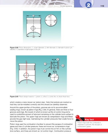
Figure 2.62 Piston dimensions: 1, crown diameter; 2, skirt diameter; 3, diameter in piston pin
direction; 4, diameter at right angles to the pin
Figure 2.63 Piston design features: 1, piston; 2, offset; 3, centre line; 4, block thrust face
which creates a noise known as ‘piston slap’. Note that pistons are marked so
that they can be installed correctly and this should be carefully observed.
Around the upper portion of the piston, grooves are cut to accommodate
sealing rings, known as piston rings ( Fig. 2.64 ). In general, there are three or four
grooves and rings, the lowest of which is known as the oil control ring and is
used to control the amount of lubricant remaining on the cylinder bore surface to
lubricate the piston. The upper rings are known as compression rings and these
provide the gas-tight seal, maintaining the cylinder pressures that create force to
Key fact
move the piston.
Piston rings seal the combustion
Piston rings seal the combustion chamber to prevent the escape of combustion chamber to prevent the escape of
gases and loss of cylinder pressure; these are known as ‘compression rings’ combustion gases.
( Fig. 2.65 ). In addition, the piston rings must control the oil fi lm on the cylinder
bore surface, and these are known as ‘oil control rings’. Combustion pressure