
Page 140 - 05. Subyek Teknik Mesin - Automobile Mechanical and Electrical Systems Automotive Technology Vehicle Maintenance and Repair (Vehicle Maintenance Repr Nv2) by Tom Denton
P. 140
2
124 Automobile mechanical and electrical systems
Figure 2.82 Head gaskets
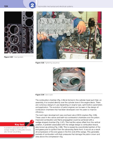
Figure 2.83 Tightening sequence
Figure 2.84 Valve seats
The combustion chamber ( Fig. 2.85 ) is formed in the cylinder head such that, on
assembly, it is located directly over the cylinder bore in the engine block. There
are numerous designs in use depending on engine type, optimization parameters
and application. The evolution of petrol engines can be seen in the design of
combustion chambers that has been developed over the years to improve
effi ciency.
The next major development was overhead valve (OHV) engines ( Fig. 2.86 ).
These used in-line valves and bath-tub combustion chambers over the piston.
Improved combustion and fl ame propagation could be achieved with a
wedge-shaped chamber ( Fig. 2.87 ). This had the valves offset from the vertical
Key fact position. A problem associated with the wedge design is combustion knock,
A problem associated with the also known as pinking ( Fig. 2.88 ). This is caused by uncontrolled ignition of the
wedge design is combustion knock, end gases prior to ignition from the advancing fl ame front. It occurs as a result
also known as pinking. of compression of the end gases in the thin end of the wedge. This generates
pockets of combustion with high pressures that damage the piston crown and
area above the compression ring.