
Page 145 - 05. Subyek Teknik Mesin - Automobile Mechanical and Electrical Systems Automotive Technology Vehicle Maintenance and Repair (Vehicle Maintenance Repr Nv2) by Tom Denton
P. 145
2
Engine systems 129
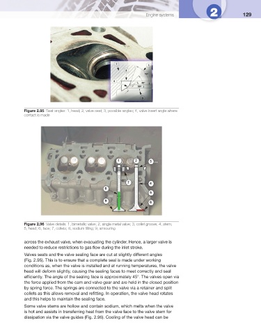
Figure 2.95 Seat angles: 1, head; 2, valve seat; 3, possible angles; 4, valve insert angle where
contact is made
1 2 3
7 4
8
5
9 6
Figure 2.96 Valve details: 1, bimetallic valve; 2, single metal valve; 3, collet groove; 4, stem;
5, head; 6, face; 7, collets; 8, sodium fi lling; 9, armouring
across the exhaust valve, when evacuating the cylinder. Hence, a larger valve is
needed to reduce restrictions to gas fl ow during the inlet stroke.
Valves seats and the valve sealing face are cut at slightly different angles
( Fig. 2.95 ). This is to ensure that a complete seal is made under working
conditions as, when the valve is installed and at running temperatures, the valve
head will deform slightly, causing the sealing faces to meet correctly and seal
effi ciently. The angle of the sealing face is approximately 45°. The valves open via
the force applied from the cam and valve gear and are held in the closed position
by spring force. The springs are connected to the valve via a retainer and split
collets as this allows removal and refi tting. In operation, the valve head rotates
and this helps to maintain the sealing face.
Some valve stems are hollow and contain sodium, which melts when the valve
is hot and assists in transferring heat from the valve face to the valve stem for
dissipation via the valve guides ( Fig. 2.96 ). Cooling of the valve head can be