
Page 148 - 05. Subyek Teknik Mesin - Automobile Mechanical and Electrical Systems Automotive Technology Vehicle Maintenance and Repair (Vehicle Maintenance Repr Nv2) by Tom Denton
P. 148
2
132 Automobile mechanical and electrical systems
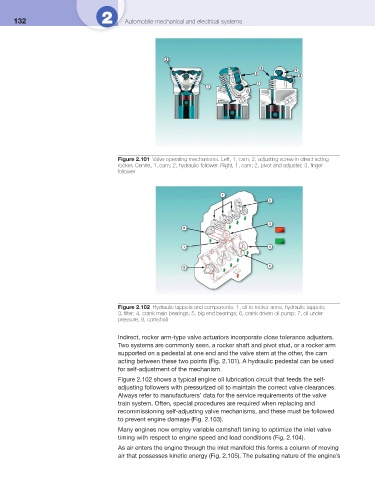
Figure 2.101 Valve operating mechanisms. Left, 1, cam; 2, adjusting screw in direct acting
rocker. Centre, 1, cam; 2, hydraulic follower. Right, 1, cam; 2, pivot and adjuster; 3, fi nger
follower
Figure 2.102 Hydraulic tappets and components: 1, oil to rocker arms, hydraulic tappets;
3, fi lter; 4, crank main bearings; 5, big end bearings; 6, crank driven oil pump; 7, oil under
pressure; 8, camshaft
Indirect, rocker arm-type valve actuators incorporate close tolerance adjusters.
Two systems are commonly seen, a rocker shaft and pivot stud, or a rocker arm
supported on a pedestal at one end and the valve stem at the other, the cam
acting between these two points ( Fig. 2.101 ). A hydraulic pedestal can be used
for self-adjustment of the mechanism.
Figure 2.102 shows a typical engine oil lubrication circuit that feeds the self-
adjusting followers with pressurized oil to maintain the correct valve clearances.
Always refer to manufacturers’ data for the service requirements of the valve
train system. Often, special procedures are required when replacing and
recommissioning self-adjusting valve mechanisms, and these must be followed
to prevent engine damage ( Fig. 2.103 ).
Many engines now employ variable camshaft timing to optimize the inlet valve
timing with respect to engine speed and load conditions ( Fig. 2.104 ).
As air enters the engine through the inlet manifold this forms a column of moving
air that possesses kinetic energy ( Fig. 2.105 ). The pulsating nature of the engine’s