
Page 150 - 05. Subyek Teknik Mesin - Automobile Mechanical and Electrical Systems Automotive Technology Vehicle Maintenance and Repair (Vehicle Maintenance Repr Nv2) by Tom Denton
P. 150
2
134 Automobile mechanical and electrical systems
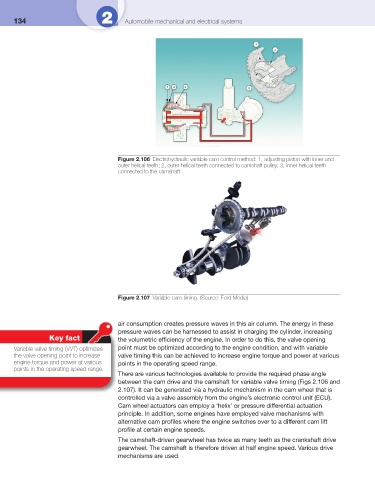
Figure 2.106 Electrohydraulic variable cam control method: 1, adjusting piston with inner and
outer helical teeth; 2, outer helical teeth connected to camshaft pulley; 3, inner helical teeth
connected to the camshaft
Figure 2.107 Variable cam timing. (Source: Ford Media)
air consumption creates pressure waves in this air column. The energy in these
pressure waves can be harnessed to assist in charging the cylinder, increasing
Key fact the volumetric effi ciency of the engine. In order to do this, the valve opening
Variable valve timing (VVT) optimizes point must be optimized according to the engine condition, and with variable
the valve opening point to increase valve timing this can be achieved to increase engine torque and power at various
engine torque and power at various points in the operating speed range.
points in the operating speed range.
There are various technologies available to provide the required phase angle
between the cam drive and the camshaft for variable valve timing ( Figs 2.106 and
2.107 ). It can be generated via a hydraulic mechanism in the cam wheel that is
controlled via a valve assembly from the engine’s electronic control unit (ECU).
Cam wheel actuators can employ a ‘helix’ or pressure differential actuation
principle. In addition, some engines have employed valve mechanisms with
alternative cam profi les where the engine switches over to a different cam lift
profi le at certain engine speeds.
The camshaft-driven gearwheel has twice as many teeth as the crankshaft drive
gearwheel. The camshaft is therefore driven at half engine speed. Various drive
mechanisms are used.