
Page 261 - 05. Subyek Teknik Mesin - Automobile Mechanical and Electrical Systems Automotive Technology Vehicle Maintenance and Repair (Vehicle Maintenance Repr Nv2) by Tom Denton
P. 261
2
Engine systems 245
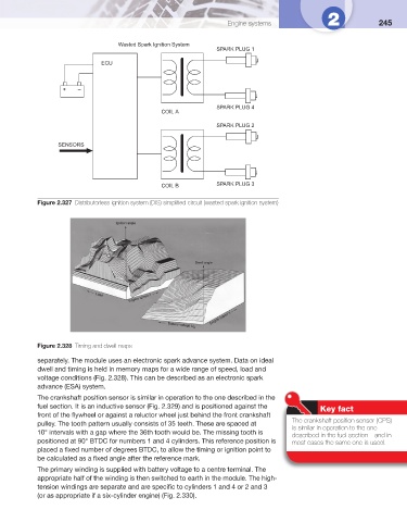
Wasted Spark Ignition System
SPARK PLUG 1
ECU
+ –
SPARK PLUG 4
COIL A
SPARK PLUG 2
SENSORS
COIL B SPARK PLUG 3
Figure 2.327 Distributorless ignition system (DIS) simplifi ed circuit (wasted spark ignition system)
Figure 2.328 Timing and dwell maps
separately. The module uses an electronic spark advance system. Data on ideal
dwell and timing is held in memory maps for a wide range of speed, load and
voltage conditions ( Fig. 2.328 ). This can be described as an electronic spark
advance (ESA) system.
The crankshaft position sensor is similar in operation to the one described in the
fuel section. It is an inductive sensor ( Fig. 2.329 ) and is positioned against the
Key fact
front of the fl ywheel or against a reluctor wheel just behind the front crankshaft
The crankshaft position sensor (CPS)
pulley. The tooth pattern usually consists of 35 teeth. These are spaced at
is similar in operation to the one
10° intervals with a gap where the 36th tooth would be. The missing tooth is
described in the fuel section – and in
positioned at 90° BTDC for numbers 1 and 4 cylinders. This reference position is most cases the same one is used.
placed a fi xed number of degrees BTDC, to allow the timing or ignition point to
be calculated as a fi xed angle after the reference mark.
The primary winding is supplied with battery voltage to a centre terminal. The
appropriate half of the winding is then switched to earth in the module. The high-
tension windings are separate and are specifi c to cylinders 1 and 4 or 2 and 3
(or as appropriate if a six-cylinder engine) ( Fig. 2.330 ).