
Page 10 - Automotive Engineering Powertrain Chassis System and Vehicle Body
P. 10
CH AP TER 1 .1 Piston-engine cycles of operation
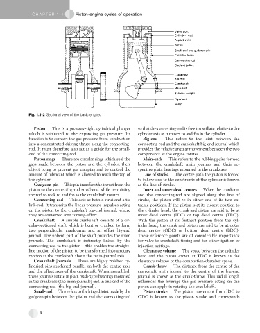
Fig. 1.1-2 Sectional view of the basic engine.
Piston This is a pressure-tight cylindrical plunger so that the connecting-rod is free to oscillate relative to the
which is subjected to the expanding gas pressure. Its cylinder axis as it moves to and fro in the cylinder.
function is to convert the gas pressure from combustion Big-end This refers to the joint between the
into a concentrated driving thrust along the connecting- connecting-rod and the crankshaft big-end journal which
rod. It must therefore also act as a guide for the small- provides the relative angular movement between the two
end of the connecting-rod. components as the engine rotates.
Piston rings These are circular rings which seal the Main-ends This refers to the rubbing pairs formed
gaps made between the piston and the cylinder, their between the crankshaft main journals and their re-
object being to prevent gas escaping and to control the spective plain bearings mounted in the crankcase.
amount of lubricant which is allowed to reach the top of Line of stroke The centre path the piston is forced
the cylinder. to follow due to the constraints of the cylinder is known
Gudgeon-pin This pin transfers the thrust from the as the line of stroke.
piston to the connecting-rod small-end while permitting Inner and outer dead centres When the crankarm
the rod to rock to and fro as the crankshaft rotates. and the connecting-rod are aligned along the line of
Connecting-rod This acts as both a strut and a tie stroke, the piston will be in either one of its two ex-
link-rod. It transmits the linear pressure impulses acting treme positions. If the piston is at its closest position to
on the piston to the crankshaft big-end journal, where the cylinder head, the crank and piston are said to be at
they are converted into turning-effort. inner dead centre (IDC) or top dead centre (TDC).
Crankshaft A simple crankshaft consists of a cir- With the piston at its furthest position from the cyl-
cular-sectioned shaft which is bent or cranked to form inder head, the crank and piston are said to be at outer
two perpendicular crank-arms and an offset big-end dead centre (ODC) or bottom dead centre (BDC).
journal. The unbent part of the shaft provides the main These reference points are of considerable importance
journals. The crankshaft is indirectly linked by the for valve-to-crankshaft timing and for either ignition or
connecting-rod to the piston – this enables the straight- injection settings.
line motion of the piston to be transformed into a rotary Clearance volume The space between the cylinder
motion at the crankshaft about the main-journal axis. head and the piston crown at TDC is known as the
Crankshaft journals These are highly finished cy- clearance volume or the combustion-chamber space.
lindrical pins machined parallel on both the centre axes Crank-throw The distance from the centre of the
and the offset axes of the crankshaft. When assembled, crankshaft main journal to the centre of the big-end
these journals rotate in plain bush-type bearings mounted journal is known as the crank-throw. This radial length
in the crankcase (the main journals) and in one end of the influences the leverage the gas pressure acting on the
connecting-rod (the big-end journal). piston can apply in rotating the crankshaft.
Small-end Thisreferstothehingedjointmadebythe Piston stroke The piston movement from IDC to
gudgeon-pin between the piston and the connecting-rod ODC is known as the piston stroke and corresponds
4