
Page 13 - Automotive Engineering Powertrain Chassis System and Vehicle Body
P. 13
Piston-engine cycles of operation CHAPTER 1.1
piston seals off the transfer port, and then a short time
later the exhaust port will be completely closed. Further
inward movement of the piston will compress the mix-
ture of air and atomised petrol to about one-seventh to
one-eighth of its original volume (Fig. 1.1-5(b)).
At the same time as the fresh charge is being com-
pressed between the combustion chamber and the piston
head, the inward movement of the piston increases the
total volume in the crank-case so that a depression is
created in this space. About half-way up the cylinder
stroke, the lower part of the piston skirt will uncover the
inlet port (I), and a fresh mixture of air and petrol pre-
pared by the carburettor will be induced into the crank-
case chamber (Fig. 1.1-5(b)).
Cylinder combustion and crankcase compression
(Fig. 1.1-5(c)) Just before the piston reaches the top
of its stroke, a spark-plug situated in the centre of the
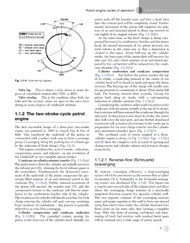
Fig. 1.1-4 Valve timing diagram.
cylinder head will be timed to spark and ignite the dense
mixture. The burning rate of the charge will rapidly raise
Valve lag This is where a valve closes so many de- the gas pressure to a maximum of about 50 bar under full
grees of crankshaft rotation after TDC or BDC. load. The burning mixture then expands, forcing the
Valve overlap This is the condition when both the piston back along its stroke with a corresponding
inlet and the exhaust valves are open at the same time reduction in cylinder pressure (Fig. 1.1-5(c)).
during so many degrees of crankshaft rotation. Considering the condition underneath the piston in the
crankcase, with the piston initially at the top of its stroke,
fresh mixture will have entered the crankcase through the
1.1.2 The two-stroke-cycle petrol
inlet port. As the piston moves down its stroke, the piston
engine skirt will cover the inlet port, and any further downward
movement will compress the mixture in the crankcase in
The first successful design of a three-port two-stroke preparation for the next charge transfer into the cylinder
engine was patented in 1889 by Joseph Day & Son of and combustion-chamber space (Fig. 1.1-5(c)).
Bath. This employed the underside of the piston in The combined cycle of events adapted to a three-
conjunction with a sealed crank-case to form a scavenge cylinder engine is shown in Fig. 1.1-5(d). Figs. 1.1-5(e)
pump (‘scavenging’ being the pushing-out of exhaust gas and (f) show the complete cycle in terms of opening and
by the induction of fresh charge) (Fig. 1.1-5). closing events and cylinder volume and pressure changes
This engine completes the cycle of events – induction, respectively.
compression, power, and exhaust – in one revolution of
the crankshaft or two complete piston strokes.
Crankcase-to-cylinder mixture transfer (Fig. 1.1-5(a)) 1.1.2.1 Reverse-flow (Schnuerle)
The piston moves down the cylinder and initially uncovers scavenging
the exhaust port (E), releasing the burnt exhaust gases to
the atmosphere. Simultaneously the downward move- To improve scavenging efficiency, a loop-scavenging
ment of the underside of the piston compresses the pre- system which became known as the reverse-flow or (after
viously filled mixture of air and atomised petrol in the its inventor, Dr E. Schnuerle) as the Schnuerle scaveng-
crankcase (Fig. 1.1-5(a)). Further outward movement of ing system was developed (Fig. 1.1-6). This layout has
the piston will uncover the transfer port (T), and the a transfer port on each side of the exhaust port, and these
compressed mixture in the crankcase will then be trans- direct the scavenging charge mixture in a practically
ferred to the combustion-chamber side of the cylinder. tangential direction towards the opposite cylinder wall.
Thesituationinthecylinderwillthenbesuchthatthefresh The two separate columns of the scavenging mixture
charge entering the cylinder will push out any remaining meet and merge together at this wall to form one inward
burnt products of combustion – this process is generally rising flow which turns under the cylinder head and then
referred to as cross-flow scavenging. flows down on the entry side, thus forming a complete
Cylinder compression and crankcase induction loop. With this form of porting, turbulence and inter-
(Fig. 1.1-5(b)) The crankshaft rotates, moving the mixing of fresh fuel mixture with residual burnt gases
piston in the direction of the cylinder head. Initially the will be minimal over a wide range of piston speeds.
7