
Page 150 - Automotive Engineering Powertrain Chassis System and Vehicle Body
P. 150
Battery/fuel-cell EV design packages CHAPTER 6.1
carbon. Working voltage is about 1.2 Vand storable energy motor/generator it acts as a load leveller, taking in power
is thus 50 J/g or 14 Wh/kg. in periods of low demand on the vehicle and contrib-
The view at (b) shows a cell cross-section, the con- uting power for hill climbing or high acceleration per-
ductive rubber having 0.2 S/cm conductivity and thick- formance demands.
ness of 20 microns. The sulphuric acid electrolyte has European research work into flywheel storage systems
conductivity of 0.7 S/cm. The view at (c) shows the high includes that reported by Van der Graaf at the Technical
3
power EDLC suitable for a hybrid vehicle, and the table at University of Eindhoven . Rather than using continu-
3
(d) its specification. Plate size is 68 48 1mm and the ously variable transmission ratio between flywheel and
weight 2.5 g, a pair having 300 F capacity. The view at driveline, a two-mode system is involved in this work. A
(e) shows constant power discharge characteristics and slip coupling is used up to vehicle speeds of 13 km/h,
(f) compares the EDLC’s energy density with that of when CVT comes in and upshifts when engine and fly-
other batteries. Fuji Industries’ ELCAPA hybrid vehicle, wheel speed fall simultaneously. At 55 km/h the drive is
(g), uses two EDLCs (of 40 F total capacity) in parallel transferred from the first to the second sheave of the
with lead–acid batteries. The stored energy can accelerate CVT variator, the engine simultaneously being linked to
the vehicle to 50 kph in a few seconds and energy is the first sheave. Thus a series hybrid drive exists at lower
recharged during regenerative braking. When high energy speeds and a parallel hybrid one at higher speeds. The
batteries are used alongside the supercapacitors, the au- 19 kg 390 mm diameter composite-fibre flywheel has
thors predict that full competitive road performance will energy content of 180 kW and rotates up to 19 000 rpm.
be obtainable.
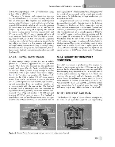
6.1.2.8 Flywheel energy storage 6.1.3 Battery car conversion
technology
Flywheel energy storage systems for use in vehicle
propulsion has reached application in the light tram For OEM conversions of production petrol-engined ve-
vehicle. They have also featured in pilot-production hicles in the decades up to the 1970s, and up to the
vehicles such as the Chrysler Patriot hybrid-drive racing present day for aftermarket conversions, are typified by
car concept. Here, flywheel energy storage is used in those used by many members of the UK Battery Vehicle
conjunction with a gas turbine prime-mover engine, Society and documented by Prigmore et al. Such con-
4
Fig. 6.1-8. The drive was developed by Satcon Tech- versions rely on basic lead–acid batteries available at
nologies in the USA to deliver 370 kW via an electric motor factors for replacement starter batteries. A ton of
motor drive to the road wheels. A turbine alternator such batteries, at traction power loading of 10–15 kW/
unit is also incorporated which provides high frequency ton, stores little more than 20 kWh. Affordable motors
current generation from an electrical machine on
and transmissions for this market sector have some 70%
a common shaft with the gas turbine. The flywheel
efficiency, to give only 14 kWh available at the wheels.
is integral with a motor/generator and contained in
a protective housing affording an internal vacuum envi-
ronment. The 57 kg unit rotates at 60 000 rpm and 6.1.3.1 Conversion case study
provides 4.3 kW of electrical energy. The flywheel is
a gimbal-mounted carbon-fibre composite unit sitting in The level-ground range of the vehicle can be expressed
a carbo-fibre protective housing. In conjunction with its in terms of an equivalent gradient 1:h, representing
Fig. 6.1-8 Chrysler Patriot flywheel energy storage system: left, turbine: right, flywheel.
151