
Page 153 - Automotive Engineering Powertrain Chassis System and Vehicle Body
P. 153
CH AP TER 6 .1 Battery/fuel-cell EV design packages
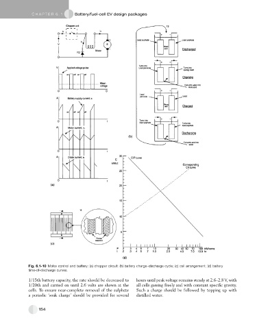
Fig. 6.1-10 Motor control and battery: (a) chopper circuit: (b) battery charge–discharge cycle; (c) cell arrangement; (d) battery
time-of-discharge curves.
1/15th battery capacity, the rate should be decreased to hours until peak voltage remains steady at 2.6–2.8 V, with
1/20th and carried on until 2.6 volts are shown at the all cells gassing freely and with constant specific gravity.
cells. To ensure near-complete removal of the sulphate Such a charge should be followed by topping up with
a periodic ‘soak charge’ should be provided for several distilled water.
154