
Page 161 - Automotive Engineering Powertrain Chassis System and Vehicle Body
P. 161
CH AP TER 6 .1 Battery/fuel-cell EV design packages
6.1.6 Electric van and truck design has since been carried over to the Ford Ecostar, described
later. Dimensions of the battery were 1520 1065 460
6.1.6.1 Goods van to fleet car conversion mm and it was based on the use of small (10 Ah) cells
connected in 4-cell series strings with parallel 8 V banks
Europe’s largest maker of EVs is Peugeot-Citroen whose arranged to provide the required capacity. Avoltage of 200
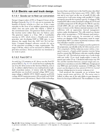
Berlingo Dynavolt, Fig. 6.1-18, sets out to maximize the required 96 cells in series (each had a voltage of 2.076) and
benefits of electric vehicles in a fleet car. It has a range a parallel arrangement of 30 cells gave the 300 Ah capacity;
extender in the form of an auxiliary generating system overall 2880 cells are used and their discharge perfor-
which does not quite make the vehicle a hybrid in mance is shown at (b). Battery internal resistance was 30
the conventional sense. The generator feeds current into milliohms with an appropriate thermal management
the traction motor rather than into the battery pack. system under development. The cells rested on a heater
The generator engine is a 16 ps, 500 cc Lombardini plate which incorporates a 710 W element used particu-
running on LPG which drives a Dynalto-style starter larly in the initial warm-up. An associated air cooling
generator unit developing 8 kW at 3300 rpm, to sup- system can dissipate 6 kW. Temperature must be main-
plement the supply from the 4 kW Saft Ni–Cad bat- tained above 300 C to achieve an internal resistance value
teries. Company designed software controls the cut-in that will allow sensible current flow.
of the generator according to range requirements. The The US General Electric Company was also a partner in
range is 80 km, which can be extended to 260 km with theprogramme, specifically ontheAC drive system, at(c).
generator assistance. Series production was imminent as This comprised a 50 bhp induction motor within a two-
we went to press. speed transaxle, a liquid-cooled transistor inverter being
used to convert the 200 battery volts into variable-voltage
3 phase AC, (d). The induction motor was a 2 pole design
6.1.6.2 Ford EXT II with just under 13 cm stack length–within a stator di-
ameter just under 23 cm. Calculated stall torque was 104
An early key US initiative in AC drives was the Ford EV Nm and the transition between constant torque and con-
project EXT11, Fig. 6.1-19, which has been exploring the stantpower operationoccurredat3800 rpm. Designspeed
use of an AC drive motor in the Aerostar Minivan, seen at was 9000 rpm and absolute maximum 12 000 rpm. Full
(a). A sodium–sulphur battery was employed and a single- power was developed at a line current of 244.5 A. Control
shaft propulsion system. A battery with the following strategy relating inverter to motor is shown at (e).
specification was involved: nominal voltage 200 V; mini- Ford produced the transaxle on an in-house basis
mum voltage at 60 kW, 135 V; 50 kW capacity on FUDS having coaxial motor and drive, (f). The motor rotor is
cycling; 60 kW maximum power (20 seconds) and 35 kW hollow to allow one of the axle shafts to pass through it
continuous power (40 minutes). Much of the technology from the bevel-gear differential. The installation in a test
Fig. 6.1-18 Citroen Berlingo Dynavolt: 1. electric motor and drive; 2. traction battery pack; 3. generator set; 4. motor controller;
5. generator controller; 6. drive programme selector; 7. LPG regulator; 8. LPG storage tank.
162