
Page 297 - Automotive Engineering Powertrain Chassis System and Vehicle Body
P. 297
CHAP TER 1 0. 1 Tyres and wheels
Fig. 10.1-16 Factor k v , which expresses the speed dependence of the rolling circumference of passenger vehicle radial tyres
above 60 km h 1 as a percentage. The permissible tolerances Dk v have to be added (see Section 10.1.2.8), all taken from the
German WDK Guideline 107, page 1.
a value which shows the extent to which the tyre be- The slip should be added directly to this, which in
comes upright when the vehicle is being driven: r dyn is direct gear amounts to around 2% (see Equations 10.1.1b
only 9 mm or 6 mm less than OD T /2. and 10.1.4f), in other words
S X;W;a ¼ 0:02
10.1.2.9 Influence of the tyre on the
speedometer If the manufacturer fully utilizes the advance specified in
Equation 10.1.2a, it is possible that although the speed-
1
ometer indicates 140 km h , the vehicle is only moving
The speedometer is designed to show slightly more than, 1
and under no circumstances less than, the actual speed. at 120 km h . This occurs, in particular, when the tyres
Tyres influence the degree of advance, whereby the fol- are worn:
lowing play a role: 3 mm wear gives an advance of around 1%
the degree of wear Tyres with an M & S winter profile can, however, have a 1%
the tolerances of the rolling circumference larger outside diameter so that the profile can be deeper
the profile design (Fig. 10.1-15, note 5 and Fig. 10.1-19). They would
associated slip. therefore reduce the degree by which the speedometer is
advanced if the tyres are not yet worn. The same applies
The EC Council directive 75/443, in force since 1991, where the positive tolerances given in the above table are
specifies an almost linear advance Dv, used. In this instance, it is also possible that even a very
precise speedometer could display too low a speed.
þDv 0:1 v þ 4 ðkm h 1 Þ (10.1.2a)
10.1.2.10 Tyre profiles
On vehicles registered from 1991 onwards the values
displayed may only be as follows: The design of tyre profiles (Fig. 10.1-19) depends on the
intended use, taking into account the parameters of
height-to-width ratio, construction and mixture and
1
Actual speed (km h ) 30 60 120 180 240 design. The aquaplaning properties are improved by in-
1
Max displayed value (km h ) 37 70 136 202 268 creasing the negative proportion (light places in the tyre
impression, Fig. 10.1-9). The shoulder region with its
As Fig. 10.1-15 indicates, at 60 km h 1 the rolling circum- transverse water-drainage grooves is particularly impor-
ferenceC R has atolerancerangeofDC R ¼þ1.5%to 2.5%, tant for its properties in a lateral direction and the middle
and according to Fig. 10.1-16 with a speed factor of k v , region with straight longitudinal grooves is important
deviations of up to Dk v ¼ 1.6% are possible. When
related to the dynamic rolling circumference C R,dyn
(Equation 10.1.1d), the following tolerance limits
(rounded to the nearest figure) may prevail and result in
the displayed values when only the minus tolerances are
considered, and if the speedometer has the maximum
authorized advance:
1
Actual speed (km h ) 60 120 180 240
Possible overall þ1.5 þ1.7 þ2.2 þ3.1
tolerance (%) 2.5 2.7 3.2 4.1
Max display value 72 140 208 279
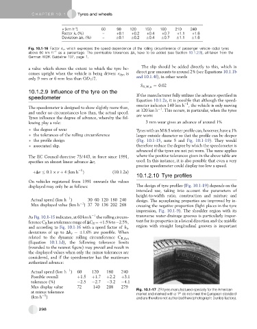
at minus tolerance Fig. 10.1-17 ZR tyres manufactured specially for the American
market and marked with a ‘P’ do not meet the European standard
1
(km h ) and are therefore not authorized here (photograph: Dunlop factory).
298