
Page 300 - Automotive Engineering Powertrain Chassis System and Vehicle Body
P. 300
Tyres and wheels C HAPTER 10.1
Sheets 2 and 3 of DIN 7817 specify the dimensions of
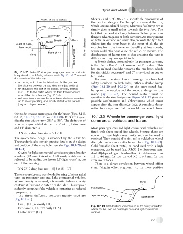
Width of cross section
the first two designs. The ‘hump’ runs around the rim,
which is rounded in H designs, whereas a flat hump rim is
simply given a small radius towards the tyre foot. The
fact that the bead sits firmly between the hump and rim
Jaw width flange is advantageous on both contours. An arrangement
Shoulder Horn on both the outside and inside also prevents the tyre feet
Hump
Height of horn sliding into the drop bases in the event of all the air
Base depth Outer diameter escaping from the tyre when travelling at low speeds,
Rim diameter difficult and requires special tools.
Base of rim which could otherwise cause the vehicle to swerve. The
Valve disadvantage of hump rims is that changing the tyre is
A French design, intended only for passenger car rims,
is the ‘Contre Pente’ rim, known as the CP for short. This
has an inclined shoulder towards the rim base, which
00
00
Fig. 10.1-20 Series 55 wide tyre designs, mounted on a double for rim widths between 4 and 6 is provided on one or
hump rim with the inflating valve shown in Fig. 10.1-6. The actual both sides.
rim consists of the following:
For years, the rims of most passenger cars have had
rim horns, which form the lateral seat for the tyre bead safety shoulders on both sides, either a double hump
(the distance between the two rims is the jaw width a); (Figs. 10.1-20 and 10.1-24) or the sharp-edged flat-
rim shoulders, the seat of the beads, generally inclined hump on the outside and the rounder design on the
at 5 1 to the centre where the force transfer occurs
around the circumference (Fig. 10.1-5); inside (Fig. 10.1-23). The desired contour must be
well base (also known as the inner base), designed as a drop specified in the rim designation. Figure 10.1-22 gives the
rim to allow tyre fitting, and mostly shifted to the outside possible combinations and abbreviations which must
(diagram: Hayes Lemmerz). appear after the rim diameter data. A complete desig-
nation for an asymmetrical rim would then be as follows:
the inside, creates more space for the brake (Figs. 8.1-8,
8.1-56, 10.1-10, 10.1-11 and 10.1-20). DIN 7817 spec- 10.1.3.3 Wheels for passenger cars, light
00
00
ifies the rim widths from 3½ to 8½ . The definition of commercial vehicles and trailers
00
a normal asymmetrical rim with a 5 width, J rim flange
00
and 14 diameter is: Most passenger cars and light commercial vehicles are
fitted with sheet metal disc wheels, because these are
DIN 7817 drop base rim 5J 14
economic, have high stress limits and can be readily
The symmetrical design is identified by the suffix ‘S’. serviced. They consist of a rim and a welded-on wheel
The standards also contain precise details on the design disc (also known as an attachment face, Fig. 10.1-23).
and position of the valve hole (see also Figs. 10.1-20 and Cold-formable sheet metal, or band steel with a high
10.1-24). elongation, can be used (e.g. RSt37-2 to European stan-
C tyres for light commercial vehicles require a broader dard 20) depending on the wheel load, in thicknesses from
shoulder (22 mm instead of 19.8 mm), which can be 1.8 to 4.0 mm for the rim and 3.0 to 6.5 mm for the
referred to by adding the letters LT (light truck) at the attachment faces.
end of the marking: There is a direct correlation between wheel offset
1
DIN 7817 drop base rim 5 J 15 LT e and ‘kingpin offset at ground’ r s ; the more positive
2
There is a preference worldwide for using tubeless radial
tyres on passenger cars and light commercial vehicles.
Where these tyres are used, it is essential to have a ‘safety
contour’ at least on the outer rim shoulder. This stops air
suddenly escaping if the vehicle is cornering at reduced
tyre pressure.
The three different contours mainly used are
(Fig. 10.1-21):
Hump (H, previously H1)
Fig. 10.1-21 Standard rim and contours of the safety shoulders
Flat-hump (FH, previously FHA) which can be used on passenger cars and light commercial
Contre Pente (CP) vehicles.
301