
Page 303 - Automotive Engineering Powertrain Chassis System and Vehicle Body
P. 303
CHAP TER 1 0. 1 Tyres and wheels
Fig. 10.1-26 Depression design with special springing
characteristics on a passenger car sheet metal disc-type wheel.
The wheel can be centred using the fixing bolts or by fitting into the
toleranced hole (Fig. 10.1-24).
00
00
using a 14 or 15 wheel should make for the best com-
promise (Figs. 8.1-1, 8.1-41, 8.1-44 and 10.1-10).
German standard DIN 74361 contains further details.
The brake disc can also be fixed to the wheel hub from
the inside (Fig. 8.1-38). However, the disadvantage of this
is that the hub has to be removed before the disc can be
changed. This is easy on the non-driven axle, but time-
consuming on the driven axle (see Section 10.1.5). This
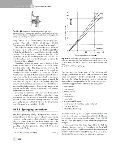
brief look shows that even the brakes play a role in the Fig. 10.1-27 The static tyre spring rate c T is the quotient of the
problems of fixing wheels. force and the deflection travel shown on the radial tyre 175/70 R
Nowadays, wheels are almost always fixed with four 13 80 S at p T ¼ 1.8 bar, 2.1 bar and 2.4 bar; the example shown
gives:
or five metric M12 1.5 or M14 1.5 DIN 74361 c T ¼ DF Z;W ¼ 1000N ¼ 167 N=mm
6 mm
spherical collar bolts. The high friction between the Ds T
spherical collar and the stud hole prevents the bolts from
coming loose while the vehicle is in motion. For this The parameter c T forms part of the vibration and
reason, some car manufacturers keep the contact surface damping calculation and has a critical influence on the
free of paint. On sheet metal disc wheels with attach- wheel load impact factor (see Section 9.1.1). The stiffer
ment faces up to 6.5 mm thick, the spring action of the the tyre, the higher the damping must be set and the
hole surround (Fig. 10.1-26) is an additional safety fea- greater the stress experienced by the chassis components.
ture, which also reduces the stress on the wheel bolts as The following parameters influence the spring rate:
a result of its design elasticity. Sheet metal rings are often vertical force
inserted in the alloy wheels to withstand high stresses tyre pressure
underneath the bolt head. driving speed
Generally, the spherical collar nuts also do the job of
centring the wheels on the hub. Hub centring has become slip angle
increasingly popular because of a possible hub or radial camber angle
run-out and the associated steering vibrations. A toler- rim width
anced collar placed on the hub fits into the dimensioned height-to-width ratio
hole which can be seen in Fig. 10.1-24. construction of tyre (bias angle, material)
tyre wear and tear
10.1.4 Springing behaviour wheel load frequency.
As can be seen in Fig. 10.1-27, apart from in the low load
The static tyre spring rate c T – frequently also known as
spring stiffness or (in the case of a linear curve) spring range, the spring rate is independent of the load. A linear
constant – is the quotient of the change in vertical force increase can be seen as the speed increases (Figs. 10.1-16
DF Z,W in newtons and the resultant change Ds T – the and 10.1-28), which persists even when the tyre pressure
compression in mm within a load capacity range corre- changes.
During cornering, the force F Y,W shifts the belt in
sponding to the tyre pressure p T (Fig. 10.1-27; see also a lateral direction, and so it tips relative to the wheel
Section 10.1.2.5.4):
plane. This leads to a highly asymmetrical distribution of
pressure and (as can be seen from Fig. 10.1-28) to a re-
c T ¼ DF Z;W =Ds T ðN=mmÞ (10.1.3)
duction in the spring rate as the slip angles increase.
304