
Page 353 - Automotive Engineering Powertrain Chassis System and Vehicle Body
P. 353
CHAP TER 1 1. 1 Tyre characteristics and vehicle handling and stability
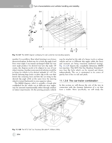
Fig. 11.1-27 The MMM diagram portraying the car’s potential manoeuvring capacity.
number 2 is a problem. Rear wheel steering is an obvious may be attached at the side of a heavy truck or railway
theoretical option. In that way, the vehicle slip angle b and vehicle and set at different slip angles while the force
front steer angle d can remain unchanged while the rear and moment are being measured (tethered testing).
steer angle produce the desired rear tyre slip angle. Of Fig. 11.1-28 depicts the remarkable laboratory MMM
course, the diagram needs to be adapted in case of rear test machine. This MTS Flat-Trac Roadway SimulatorÔ
wheel steering. Another more practical solution would be uses four flat belts which can be steered and driven
to bring the vehicle in the desired attitude (b /8 )by independently. The car is constrained in its centre of
briefly inducing large brake or drive slip at the rear that gravity but is free to roll and pitch.
lowers the cornering force and lets the car swing to the
desired slip angle while at the same time the steering
wheel is turned backwards to even negative values. 11.1.3.6 The car-trailer combination
The MMM diagram, which is actually a Gough plot
established for the whole car at different steer angles, In this section we will discuss the role of the tyre in
may be assessed experimentally either through outdoor connection with the dynamic behaviour of a car that
or indoor experiments. On the proving ground a vehicle tows a trailer. More specifically, we will study the
Fig. 11.1-28 The MTS Flat-Trac Roadway SimulatorÔ, Milliken (1995).
354