
Page 355 - Automotive Engineering Powertrain Chassis System and Vehicle Body
P. 355
CHAP TER 1 1. 1 Tyre characteristics and vehicle handling and stability
From the resulting set of linear differential equations the bad for stability. Furthermore, it has been found that
characteristic equation may be derived which is of the a larger draw bar length g is favourable for stability.
fourth degree. Its general structure is: It turns out that a second type of instability may show
up. This occurs when the portion of the weight of the
4
2
3
a 0 s þ a 1 s þ a 2 s þ a 3 s þ a ¼ 0 (11.1.117) caravan supported by the coupling point becomes too
4
large. This extra weight is felt by the towing vehicle and
The stability of the system can be investigated by
considering the real parts of the roots of this equation or makes it more oversteer. The critical speed associated
with this phenomenon is indicated in the diagram by the
we might employ the criterium for stability according to vertical lines. This divergent instability occurs when
Routh–Hurwitz. According to this criterion the system of (starting out from a stable condition) the last coefficient
order n is stable when all the coefficients a i are positive becomes negative, that is a n ¼ a 4 < 0.
and the Hurwitz determinants H n 1 , H n 3 etc. are The oscillatory instability connected with the ‘snaking’
positive. For our fourth-order system the complete phenomenon arises as soon as (from a stable condition)
criterion for stability reads: the second highest Hurwitz determinant becomes nega-
2 3
a 1 a 0 0 tive, H n 1 ¼ H 3 < 0 (then also H n < 0). When the
6 7 critical speed is surpassed self-excited oscillations are
H 3 ¼ 4 a 3 a 2 a 1 5
created which shows an amplitude that in the actual non-
0 a 4 a 3 linear case does not appear to limit itself. This is in
2
2
¼ a 1 a 2 a 3 a a a 0 a > 0 contrast to the case of the wheel shimmy phenomenon.
4
3
1
a i > 0 for i ¼ 0; 1; .; 4 (11.1.118) The cause of the unlimited snaking oscillation is that with
increasing amplitudes also the slip angle increases which
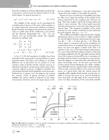
In Fig. 11.1-30, the boundaries of stability have been lowers the average cornering stiffness as a consequence of
presented in the caravan axle cornering stiffness vs speed the degressively non-linear cornering force characteristic.
parameter plane. The three curves belong to the three From the diagram we found that this will make the sit-
different sets of parameters for the position f of the uation increasingly worse. As has been seen from full
caravan’s centre of gravity and the caravan’s mass m c as vehicle/caravan model simulations, the whole combina-
indicated in the figure. An important result is that a lower tion will finally overturn. Another effect of this reduction
cornering stiffness promotes oscillatory instability: the of the average cornering stiffness is that when the vehicle
critical speed beyond which instability occurs decreases. moves at a speed lower than the critical speed, the
Furthermore, it appears from the diagram that moving originally stable straight ahead motion may become un-
the caravan’s centre of gravity forward ( f smaller) stable if through the action of an external disturbance
stabilises the system which is reflected by the larger (side wind gust) the slip angle of the caravan axle be-
critical speed. A heavier caravan (m c larger) appears to be comes too large (surpassing of the associated unstable
f = 2.0 1.7 1.7 [ m ]
m = 1200 1600 1200 [ kg ]
c
C
3
100000 stable divergent
instability
[ N/rad ]
40000
oscillatory
instability
V
0 crit
0 10 20 30 40 50 [ m/s ]
Fig. 11.1-30 Stability boundaries for the car caravan combination in the caravan cornering stiffness vs critical speed diagram. Vehicle
parameters according to Table 11.1-1, in addition:
2
h ¼ 2m, g ¼ 2m, k c ¼ 1.5 m (I c ¼ m c k c ), cf. Fig. 11.1-29.
356