
Page 704 - Automotive Engineering Powertrain Chassis System and Vehicle Body
P. 704
Interior noise: Assessment and control C HAPTER 21.1
The effect of parameters s, r, h is to lower the speed of Airborne
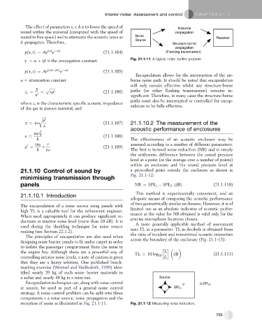
sound within the material (compared with the speed of propagation
sound in free space) and to attenuate the acoustic wave as Noise Receiver
it propagates. Therefore, Source Structure-borne
propagation
e
pðx; tÞ¼ Ae iut gx (21.1.104) (Flanking transmission)
g ¼ a þ ib is the propogation constant. Fig. 21.1-11 A typical noise control problem.
e
pðx; tÞ¼ Ae iðut bxÞ ax (21.1.105)
Encapsulation allows for the interruption of the air-
a ¼ attenuation constant borne noise path. It should be noted that encapsulation
will only remain effective whilst any structure-borne
p p ffiffiffiffiffiffi
z c ¼ ¼ kr 0 (21.1.106) paths (or other flanking transmission) remains in-
u 0 significant. Therefore, in many cases the structure-borne
paths must also be interrupted or controlled for encap-
where z c is the characteristic specific acoustic impedance
of the gas in porous material; and sulation to be fully effective.
r ffiffiffiffi
r 0
g ¼ iu (21.1.107) 21.1.10.2 The measurement of the
k
acoustic performance of enclosures
r c 2
0 0
k ¼ (21.1.108)
h The effectiveness of an acoustic enclosure may be
sr 0 r assessed according to a number of different parameters.
0
r ¼ þ (21.1.109)
h iu The first is termed noise reduction (NR) and is simply
the arithmetic difference between the sound pressure
level at a point (or the average over a number of points)
within an enclosure and the sound pressure level at
21.1.10 Control of sound by a prescribed point outside the enclosure as shown in
Fig. 21.1-12:
minimising transmission through
panels NR ¼ SPL 1 SPL 2 ðdBÞ (21.1.110)
This method is experimentally convenient, and an
21.1.10.1 Introduction
adequate means of comparing the acoustic performance
of two geometrically similar enclosures. However, it is of
The encapsulation of a noise source using panels with
high TL is a valuable tool for the refinement engineer. limited use as an absolute indicator of acoustic perfor-
When used appropriately it can produce significant re- mance as the value for NR obtained is valid only for the
ductions in interior noise level (more than 10 dB). It is precise microphone locations chosen.
used during the shielding technique for noise source A more generally applicable method of assessment
ranking (see Section 22.1.2). uses TL as a parameter. TL in decibels is obtained from
The principles of encapsulation are also used when the ratio of incident and transmitted acoustic intensities
designing noise barrier panels to fit under carpet in order across the boundary of the enclosure (Fig. 21.1-13):
to isolate the passenger compartment from the noise in
the engine bay. Although these are a powerful way of TL ¼ 10 log I i dB (21.1.111)
controlling interior noise levels, a note of caution is given 10 I t
that they are a heavy solution. One published bench-
marking exercise (Wentzel and VanBuskirk, 1999) iden-
tified nearly 39 kg of such noise barrier materials in
a sedan and nearly 48 kg in a mini-van. Source
Encapsulation techniques can, along with noise control SPL 2
at source, be used as part of a general noise control SPL 1
strategy. A noise control problem can be split into three
components – a noise source, noise propagation and the
reception of noise as illustrated in Fig. 21.1-11. Fig. 21.1-12 Measuring noise reduction.
715