
Page 709 - Automotive Engineering Powertrain Chassis System and Vehicle Body
P. 709
CHAP TER 2 1. 1 Interior noise: Assessment and control
In the case of isotropic panels there exists a frequency, frequency of the first panel resonance the TL dips and is
named the critical frequency, at which the flexural in part controlled by the damping of the system. At
wavelength in the panel matches the acoustic wavelength moderate frequencies, TL is controlled by the mass or
in the air. Orthotropic panels will have more than one surface density of the panel and increases at a rate of 6 dB
critical frequency. The critical frequency or frequencies per octave (the so-called mass law relationship) up to
in either case are given by (Bies and Hansen, 1996): the coincidence dip around the critical frequency. At
r ffiffiffiffiffi frequencies above the critical frequency the TL is said
c 2 m
f c ¼ Hz (21.1.130) to be damping-controlled and rises at a rate of 9 dB per
2p B 0 octave.
The corresponding typical TL curve for orthotropic
1
where c is the speed of sound in air (m s ) and m is the panels is characterised by a wide coincidence region
2
surface density (kg m ). caused by the presence of more than one critical fre-
At frequencies around the critical frequency an effect quency. For this reason orthotropic panels should be
known as coincidence is noted. At coincidence frequen- avoided when noise control is important. However, the
cies the panel is strongly coupled to the fluid so that sound TL characteristics of a heavily damped orthotropic panel
impinging on the panel from any angle of incidence will will tend towards that of an isotropic panel.
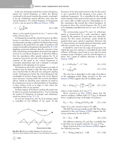
produceastrongflexuralresponseinthepanel(Fig.21.1-18). It should be noted that the range of frequencies for
Applying reciprocity indicates that the converse is true which the mass law operates is controlled by the panel
with a panel being a strong radiator of sound of any angle of stiffness. Stiffening a panel tends to move the first panel
emission at coincidence frequencies. It therefore follows
resonance f 0 up in frequency, and the critical frequency f c
that the coincidence effect greatly reduces the TL of down. For a panel of uniform thickness h (Bies and
a panel at frequencies near the critical frequencies. The Hansen, 1996)
response of the panel at the critical frequencies is
a resonant phenomena and such a response is strongly 2 2
dependent on the damping in the system. f 0 ¼ 0:453c L hða þ b Þ Hz (21.1.131)
At frequencies above the critical frequency an angle of c 2
incidence may be found so that the trace of the sound f c ¼ 1:81c L h Hz (21.1.132)
wave matches that of a flexural wave and good coupling
results. At frequencies below the critical frequency, the The mass law is dependent on the angle of incidence
wavelength of sound is longer than that of any flexural of the impinging sound. Sharp (reported in Bies and
waves and poor coupling results due to local cancellation Hansen (1996)) suggests that for an infinite panel
effects. Panels are therefore poor radiators of sound at
low frequencies except at discontinuities or boundaries pfm
2
in their surfaces (such as at edges or ribs) where the TL q ¼ 10 log 10 1 þ cosq dB (21.1.133)
cancellation effect is not present. rc
At these regions of localised coupling, the panel may 3
be driven by sound of normal incidence. Curves showing where r is the density of air (kg m ).
the typical TL behaviour of isotropic and orthotropic Pierce (reported in Fahy (1985)) shows that the
panels are shown in Fig. 21.1-19. random incidence (diffuse field) TL (TL D ) is obtained
At very low frequencies, the TL of an isotropic panel from a weighted average of all angles of incidence:
is controlled by the stiffness of the panel. At the
TL D ¼ TL N 10 log ð0:23TL N Þ dB (21.1.134)
10
where TL N is the normal incidence TL (dB).
+ The field TL is not necessarily equal to the TL D . Sharp
Airborne wave
(reported in Bies and Hansen (1996)) suggests the fol-
lowing relationship for the field TL:
–
+ + + TL ¼ TL N 5 dB (21.1.135)
The difference between TL and TL D is probably due
to the finite size of panels tested for the case of TL D .
– – – Sharp (reported in Bies and Hansen (1996)) suggests
Structure-borne wave the following mass law:
Fig. 21.1-18 Strong coupling between the airborne and
structure-borne waves occurs around the coincidence frequency. TL ¼ 20 log ½ðpfm=rcÞ 5 dB (21.1.136)
10
720