Page 713 - Automotive Engineering Powertrain Chassis System and Vehicle Body
P. 713

CHAP TER 2 1. 1       Interior noise: Assessment and control

                 The sound pressure level at a point in free space some  The problem is not so simple when the direct field is
               distance r away from the enclosure can be determined  dominant at one or more walls of the enclosure. In this
               from (Bies and Hansen, 1996):                      case, the enclosure should be treated as a barrier.

                 L WE x L p1 þ 10 log S E dB         (21.1.167)
                                  10
                                                                  21.1.10.7 Sound inside and outside
                                     D q
                    ¼ L WE þ 10 log       dB         (21.1.168)   close fitting enclosures
                                     4pr
                 L p 2            10    2
                 When the enclosure is positioned on a hard floor:  Jackson produced two useful papers on the performance
                                                                  of close fitting enclosures (Jackson, 1962; 1966). He
                 D q ¼ 2                             (21.1.169)   developed a 1-D model of such an enclosure by treating
                                                                  the noise source and the enclosure as a pair of concentric
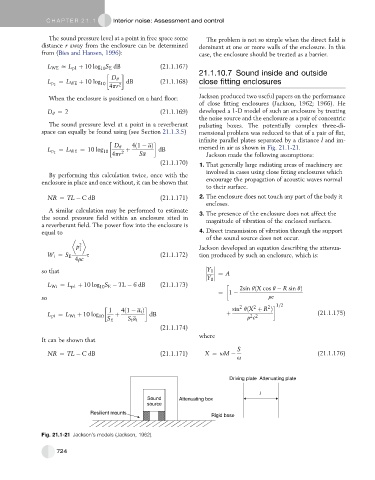
                 The sound pressure level at a point in a reverberant  pulsating boxes. The potentially complex three-di-
               space can equally be found using (see Section 21.1.3.5)  mensional problem was reduced to that of a pair of flat,
                                                                  infinite parallel plates separated by a distance l and im-
                                      D q   4ð1   aÞ              mersed in air as shown in Fig. 21.1-21.
                    ¼ L WE ¼ 10 log       þ          dB
                 L p 2             10    2
                                      4pr      Sa                   Jackson made the following assumptions:
                                                     (21.1.170)   1. That generally large radiating areas of machinery are
                                                                    involved in cases using close fitting enclosures which
                 By performing this calculation twice, once with the
               enclosure in place and once without, it can be shown that  encourage the propagation of acoustic waves normal
                                                                    to their surface.
                 NR ¼ TL   C dB                      (21.1.171)   2. The enclosure does not touch any part of the body it
                                                                    encloses.
                 A similar calculation may be performed to estimate
               the sound pressure field within an enclosure sited in  3. The presence of the enclosure does not affect the
                                                                    magnitude of vibration of the enclosed surfaces.
               a reverberant field. The power flow into the enclosure is
               equal to                                           4. Direct transmission of vibration through the support
                                                                    of the sound source does not occur.
                          p 2                                     Jackson developed an equation describing the attenua-
                           1
                 W i ¼ S E   s                       (21.1.172)   tion produced by such an enclosure, which is:
                         4rc

               so that                                                Y 1

                                                                          ¼ A
                                                                     Y 0
                 L Wi ¼ L p1 þ 10 log S E   TL   6 dB  (21.1.173)              2sin qðX cos q   R sin qÞ
                                  10
                                                                        ¼ 1
               so                                                                        rc
                                                                               2    2   2   1=2
                                     1   4ð1   a i Þ                         sin qðX þ R Þ
                 L pi ¼ L Wi þ 10 log 10  þ       dB                       þ       2 2                   (21.1.175)
                                    S E    S i a i                                r c
                                                     (21.1.174)
                                                                  where
               It can be shown that
                                                                               S
                 NR ¼ TL   C dB                      (21.1.171)     X ¼ uM                               (21.1.176)
                                                                              u


                                                                            Driving plate  Attenuating plate

                                                                                      l
                                                 Sound     Attenuating box
                                                 source
                              Resilient mounts
                                                                      Rigid base

               Fig. 21.1-21 Jackson’s models (Jackson, 1962).


                    724
   708   709   710   711   712   713   714   715   716   717   718