
Page 775 - Automotive Engineering Powertrain Chassis System and Vehicle Body
P. 775
CHAP TER 2 3. 1 Automotive instrumentation and telematics
1. Fuel quantity
2. Fuel pump pressure
3. Fuel flow rate
4. Vehicle speed
5. Oil pressure
Fig. 23.1-1 General instrumentation block diagram. 6. Oil quantity
7. Coolant temperature
8. Outside ambient temperature
is read by the vehicle driver. If a quantity to be measured is 9. Windshield washer fluid quantity
already in electrical form (e.g., the battery charging
current) this signal can be used directly and no sensor is 10. Brake fluid quantity
required.
In some modern automotive instrumentation, a In addition to these variables, the input may include
microcomputer (or related digital subsystem) performs switches for detecting open doors and trunk, as well as IP
all of the signal processing operations for several selection switches for multifunction displays that permit
measurements. The primary motivation for computer- the driver to select from various display modes or mea-
based instrumentation is the great flexibility offered in surement units. For example, the driver may be able to
the design of the instrument panel. A block diagram for select vehicle speed in miles per hour (mph) or kilometers
such an instrumentation system is shown in Fig. 23.1-2. per hour (kph).
All measurements from the various sensors and An important function of modern instrumentation
switches are processed in a special-purpose digital systems is to receive diagnostic information from cer-
computer. The processed signals are routed to the appro- tain subsystems and to display appropriate warning
priate display or warning message. It is common practice messages to the driver. The powertrain control system,
in modern automotive instrumentation to integrate the for example, continuously performs self-diagnosis op-
display or warning in a single module that may include erations. If a problem has been detected, a fault code is
both solid-state alphanumeric display, lamps for illumi- set indicating the nature and location of the fault. This
nating specific messages, and traditional electromecha- code is transmitted to the instrumentation system via
nical indicators. For convenience, this display will be a powertrain digital data line (PDDL in Fig. 23.1-2).
termed the instrument panel (IP). This code is interpreted in the instrumentation com-
The inputs to the instrumentation computer include puter and a ‘‘Check Engine’’ warning message is
sensors (or switches) for measuring (or sensing) various displayed. Similar diagnostic data are sent to the in-
vehicle variables as well as diagnostic inputs from the strumentation system from each of the subsystems for
other critical electronic subsystems. The vehicle status which driver warning messages are deemed necessary
sensors may include any of the following: (e.g., ABS, airbag, cruise control).
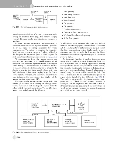
IP
VEHICLE INSTRUMENTATION DISPLAY
STATUS COMPUTER OR
SENSORS WARNING
LAMPS
CC A/B
PDDL ABS
POWER TRAIN ANTILOCK CRUISE
CONTROL BRAKE CONTROL AIRBAG
SUBSYSTEM SUBSYSTEM SUBSYSTEM SUBSYSTEM
Fig. 23.1-2 Computer-based instrumentation system.
786