
Page 776 - Automotive Engineering Powertrain Chassis System and Vehicle Body
P. 776
Automotive instrumentation and telematics C HAPTER 23.1
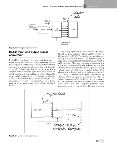
Fig. 23.1-3 Analog-to-digital conversion.
23.1.2 Input and output signal The analog inputs must all be converted to digital
format using an analog to digital (A/D) converter as
conversion
illustrated in Fig. 23.1-3. The digital inputs are, of course,
already in the desired format. The conversion process
It should be emphasized that any single input can be requires an amount of time that depends primarily on the
either digital switched or analog, depending on the A/D converter. After the conversion is complete, the
technology used for the sensor. A typical instrumentation digital output generated by the A/D converter is the
computer is an integrated subsystem that is designed to closest possible approximation to the equivalent analog
accept all of these input formats. A typical system is voltage, using an M-bit binary number (where M is
designed with a separate input from each sensor or chosen by the designer and is normally between 8 and
switch. An example of an analog input is the fuel quantity 32). The A/D converter then signals the computer by
sensor, which is normally a potentiometer attached to changing the logic state on a separate lead (labeled
a float, as described in detail later in this chapter. The ‘‘conversion complete’’ in Fig. 23.1-3) that is connected
measurement of vehicle speed given in Chapter 13.1 is an to the computer. The output voltage of each analog
example of a measurement that is already in digital sensor for which the computer performs signal
format. processing must be converted in this way. Once the
Fig. 23.1-4 Digital-to-analog conversion.
787