
Page 780 - Automotive Engineering Powertrain Chassis System and Vehicle Body
P. 780
Automotive instrumentation and telematics C HAPTER 23.1
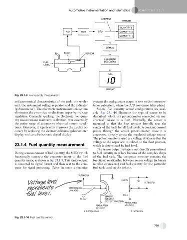
Fig. 23.1-9 Fuel quantity measurement.
and geometrical characteristics of the tank, the sender systems the analog sensor output is sent to the instrumen-
unit, the instrument voltage regulator, and the indicator tation subsystem, where the A/D conversion takes place.)
(galvanometer). The electronic instrumentation system Several fuel quantity sensor configurations are avail-
eliminates the error that results from imperfect voltage able. Fig. 23.1-10 illustrates the type of sensor to be
regulation. Generally speaking, the electronic fuel quan- described, which is a potentiometer connected via me-
tity measurement maintains calibration over essentially chanical linkage to a float. Normally, the sensor is
the entire range of automotive electrical system condi- mounted so that the float remains laterally near the
tions. Moreover, it significantly improves the display ac- center of the tank for all fuel levels. A constant current
curacy by replacing the electromechanical galvanometer passes through the sensor potentiometer, since it is
display with an all-electronic digital display. connected directly across the regulated voltage source.
The potentiometer is used as a voltage divider so that the
voltage at the wiper arm is related to the float position,
23.1.4 Fuel quantity measurement which is determined by fuel level.
The sensor output voltage is not directly proportional
During a measurement of fuel quantity, the MUX switch to fuel quantity in gallons because of the complex shape
functionally connects the computer input to the fuel of the fuel tank. The computer memory contains the
quantity sensor, as shown in Fig. 23.1-9. This sensor output functional relationship between sensor voltage (in binary
is converted to digital format and then sent to the com- number equivalent) and fuel quantity for the particular
puter for signal processing. (Note: In some automotive fuel tank used on the vehicle.
Fig. 23.1-10 Fuel quantity sensor.
791