
Page 784 - Automotive Engineering Powertrain Chassis System and Vehicle Body
P. 784
Automotive instrumentation and telematics C HAPTER 23.1
and fuel quantity gauge were originally electromechanical carriers combine with the negative carriers at the junc-
devices. Then automotive manufacturers began using tion. The diode is constructed so that the light generated
warning lamps instead of gauges to cut cost. A warning at the junction can escape from the diode and be seen.
lamp can be considered as a type of electro-optical display. An LED display is normally made of small dots or
Recent developments in solid-state technology in the rectangular segments arranged so that numbers and let-
field called optoelectronics have led to sophisticated ters can be formed when selected dots or segments are
electro-optical display devices that are capable of in- turned on. The configuration for these segments is de-
dicating alphanumeric data. This means that both scribed in greater detail later in this chapter in the section
numeric and alphabetic information can be used to dis- on VFD. A single LED is not well suited for automotive
play the results of measurements of automotive variables display use because of its low brightness. Although it can
or parameters. This capability allows messages in English be seen easily in darkness, it is difficult to impossible to
or other languages to be given to the driver. The input for see in bright sunlight. It also requires more electrical
these devices is an electronic digital signal, which power than an LCD display; however, its power re-
makes these devices compatible with computer-based quirements are not great enough to be a problem for
instrumentation, whereas electromechanical displays automotive use.
require a D/A converter.
Automobile manufacturers have considered many
different types of electronic displays for automotive in- 23.1.10 LCD
strumentation, but only four have been really practical:
light-emitting diode (LED), liquid crystal display (LCD), The LCD display is commonly used in electronic digital
vacuum-fluorescent display (VFD), and the cathode ray watch displays because of its extremely low electrical
tube (CRT). It now appears that the VFD will be the power and relatively low voltage requirements. The heart
predominant type of instrumentation for at least the near of an LCD is a special liquid that is called a twisted
future. Each of these types is discussed briefly to explain nematic liquid crystal. This liquid has the capability of
their uses in automotive applications. rotating the polarization of linearly polarized light.
Linearly polarized light has all of the vibrations of the
optical waves in the same direction. Light from the sun
23.1.9 LED and from most artificial light sources is not polarized, and
the waves vibrate randomly in many directions.
The LED is a semiconductor diode that is constructed in Nonpolarized light can be polarized by passing the
a manner and of a material so that light is emitted when light through a polarizing material. To illustrate, think of
an electrical current is passed through it. The semi- a picket fence with narrow gaps between the pickets. If
conductor material most often used for an LED that a rope is passed between two of the pickets and its end is
emits red light is gallium arsenide phosphide. Light is whipped up and down, the ripples in the rope will pass
emitted at the diode’s PN junction when the positive through the fence. The ripples represent light waves and
the picket fence represents a polarizing material. If you
whip the rope in any direction other than vertically, the
ripples will not pass through.
Now visualize another picket fenced turned 90 so
that the pickets are horizontal. Place this fence behind
the vertical picket fence. This arrangement is called
a cross-polarizer. If the rope is now whipped in any di-
rection, no ripples will pass through both fences. Simi-
larly, if a cross-polarizer is used for light, no light will pass
through this structure.
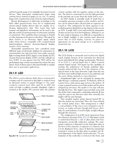
The configuration of an LCD can be understood from
the schematic drawings of Fig. 23.1-16. The liquid crystal
is sandwiched between a pair of glass plates that have
transparent, electrically conductive coatings. The trans-
parent conductor is deposited on the front glass plate in
the form of the character, or segment of a character, that
is to be displayed. Next, a layer of dielectric (insulating)
material is coated on the glass plate to produce the de-
sired alignment of the liquid crystal molecules. The po-
Fig. 23.1-16 Typical LCD construction. larization of the molecules is vertical at the front, and
795