
Page 786 - Automotive Engineering Powertrain Chassis System and Vehicle Body
P. 786
Automotive instrumentation and telematics C HAPTER 23.1
Some display manufacturers produce an LCD that phosphor on the anode, the phosphor emits light. A
combines reflective and transmissive structures in a so- common VFD has a phosphor that emits a blue-green
called transflexive LCD structure. The combination of light that provides good readability in the wide range of
these two basic LCD types into using a package permits ambient light conditions that are present in an automo-
optimal readability to be achieved for automotive dis- bile. However, other colors (e.g., red or yellow) are
plays over the entire range of ambient light conditions available by using other phosphors.
from bright sunny days to the darkest night conditions. The numeric characters are formed by shaping the
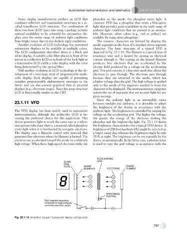
Another evolution of LCD technology has permitted anode segments in the form of a standard seven-segment
automotive displays to be available in multiple colors. character. The basic structure of a typical VFD is
The LCD configuration described above is a black and depicted in Fig. 23.1-18. The filament is a special type of
white display. A suitable color filter placed in front of the resistance wire and is heated by passing an electrical
mirror in a reflective LCD or in front of the back light in current through it. The coating on the heated filament
a transmissive LCD yields a color display, with the color produces free electrons that are accelerated by the
being determined by the optical filter. electric field produced by a voltage on the accelerating
Still another evolution in LCD technology is the de- grid. This grid consists of a fine wire mesh that allows the
velopment of a very large array of programmable multi- electrons to pass through. The electrons pass through
color display. Such displays are capable of presenting because they are attracted to the anode, which has
complex programmable alphanumeric messages to the a higher voltage than the grid. The high voltage is applied
driver and can also present graphical data or pictorial only to the anode of the segments needed to form the
displays (e.g., electronic maps). Since the array structure character to be displayed. The instrumentation computer
LCD is functionally similar to the CRT . selects the set of segments that are to emit light for any
given message.
Since the ambient light in an automobile varies
23.1.11 VFD between sunlight and darkness, it is desirable to adjust
the brightness of the display in accordance with the
The VFD display has been widely used in automotive ambient light. The brightness is controlled by varying the
instrumentation, although the multicolor LCD is be- voltage on the accelerating grid. The higher the voltage,
coming the preferred choice for this application. This the greater the energy of the electrons striking the
device generates light in much the same way as a televi- phosphor and the brighter the light. Fig. 23.1-19 shows
sion picture tube does; that is, a material called phosphor the brightness characteristics for a typical VFD device. A
emits light when it is bombarded by energetic electrons. brightness of 200 foot-lamberts (fL) might be selected on
The display uses a filament coated with material that a bright sunny day, whereas the brightness might be only
generates free electrons when the filament is heated. The 20 fL at night. The brightness can be set manually by the
electrons are accelerated toward the anode by a relatively driver, or automatically. In the latter case, a photoresistor
high voltage. When these high-speed electrons strike the is used to vary the grid voltage in accordance with the
Fig. 23.1-18 Simplified vacuum-fluorescent display configuration.
797