
Page 790 - Automotive Engineering Powertrain Chassis System and Vehicle Body
P. 790
Automotive instrumentation and telematics C HAPTER 23.1
a solid-state raster scan display device is to construct an The intensity and/or color of the active LCD is con-
array of LCD elements as depicted in Fig. 23.1-20b. trolled by a signal connected to that LCD. The appro-
These elements are interconnected with two grids of priate signal is known as the video signal.
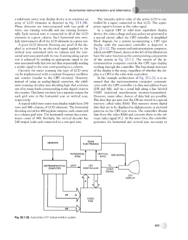
wires, one running vertically and one running horizon- In a typical CRT or solid-state equivalent display
tally. Each vertical wire is connected to all of the LCD device, the video voltage and sync pulses are generated in
elements in a given column. Each horizontal wire simi- a special circuit called the CRT controller. A simplified
larly interconnects all of the LCD elements in a given row. block diagram for a system incorporating a CRT type
A given LCD element (forming one pixel of the dis- display with the associated controller is depicted in
play) is activated by an electrical signal applied to the Fig. 23.1-22. The sensors and instrumentation computer,
vertical wire associated with its column and the hori- which are MPU based, shown at the left of this illustration
zontal wire associated with its row. Scanning along a given have the same function as the corresponding components
row is achieved by sending an appropriate signal to the of the system in Fig. 23.1-2. The output of the in-
wire associated with that row and then sequentially sending strumentation computer controls the CRT type display,
a similar signal to the wire corresponding to a column. working through the controller. The functional structure
Circuitry for raster scanning this type of LCD array of the display is the same, regardless of whether the dis-
can be implemented with a constant frequency oscillator play is a CRTor the solid-state equivalent.
and counter (similar to the CRT circuitry). However, In the example architecture of Fig. 23.1-22, it is as-
instead of using an analog/digital converter, the solid- sumed that the instrumentation computer communi-
state scanning circuitry uses decoding logic that activates cates with the CRTcontroller via data and address buses
one of its many leads corresponding to the digital count in (DB and AB), and via a serial link along a line labeled
the counter. This latter circuitry has a separate output for UART (universal asynchronous receiver/transmitter).
each grid wire in the horizontal scan or vertical scan, However, many other choices of data link are possible.
respectively. The data that are sent over the DB are stored in a special
A typical solid-state raster scan display might have 240 memory called video RAM. This memory stores digital
rows and 480 columns of LCD elements. The horizontal data that are to be displayed in alphanumeric or pictorial
decoding circuit has 480 separate outputs, each connected patterns on the CRT-type screen. The controller obtains
to a column grid wire. The horizontal counter has a max- data from the video RAM and converts them to the rel-
imum count of 480. Similarly, the vertical decoder has evant video signal (V c ). At the same time, the controller
240 output leads each connected to a row grid wire. generates the horizontal and vertical sync necessary to
Fig. 23.1-22 Automotive CRT instrumentation system.
801