
Page 792 - Automotive Engineering Powertrain Chassis System and Vehicle Body
P. 792
Automotive instrumentation and telematics C HAPTER 23.1
A scheme for generating the suitable video signals for available to the driver, the CRT type display can present
such a display is shown in a greatly simplified hypothet- engine data for diagnostic purposes vehicle comfort
ical example of a black and white solid-state display in control system parameters, and entertainment system
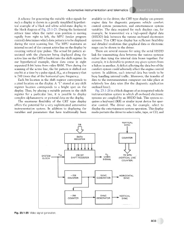
the block diagram of Fig. 23.1-25. During the horizontal variables. The data required for such displays can, for
retrace time when the raster scan position is moving example, be transmitted via a high-speed digital data
rapidly from right to left, the MPU (under program (HSDD) link between the various on-board electronics
control) determines which data pattern is to be displayed systems. This CRT-type display has sufficient flexibility
during the next scanning line. The MPU maintains an and detailed resolution that graphical data or electronic
internal record of the current active line on the display by maps can be shown to the driver.
counting vertical sync pulses. The actual bit pattern as- There are several reasons for using the serial HSDD
sociated with the character being displayed along the link for transmitting data between the various systems
active line on the CRT is loaded into the shift register. In rather than tying the internal data buses together. For
our hypothetical example, these data come in eight example, it is desirable to protect any given system from
separated 8-bit bytes from video RAM. Then during the a failure in another. A defect affecting the data bus of the
scanning of the active line, the bit pattern is shifted out comfort system could adversely affect the engine control
one bit at a time by a pulse signal, H ck , at a frequency that system. In addition, each internal data bus tends to be
is 240 times that of the horizontal sync frequency. busy handling internal traffic. Moreover, the transfer of
Each bit location in the shift register corresponds to data to the instrumentation computer can take place at
a pixel location on the display. A ‘‘1’’ stored at any shift relatively low data rates (for the diagnostic application
register location corresponds to a bright spot on the outlined here).
display. Thus, by placing a suitable pattern in the shift Fig. 23.1-26 is a block diagram of an integrated vehicle
register for a particular line, it is possible to display instrumentation system in which all on-board electronic
complex alphanumeric or pictorial data on the display. systems are coupled by an HSDD link. This system re-
The enormous flexibility of the CRT type display quires a keyboard (KB) or similar input device for oper-
offers the potential for a very sophisticated automotive ator control. The driver can, for example, select to
instrumentation system. In addition to displaying the display the entertainment system operation. This display
variables and parameters that have traditionally been mode permits the driver to select radio, tape, or CD, and
Fig. 23.1-25 Video signal generation.
803