
Page 791 - Automotive Engineering Powertrain Chassis System and Vehicle Body
P. 791
CHAP TER 2 3. 1 Automotive instrumentation and telematics
Fig. 23.1-23 CRT-type controller configuration.
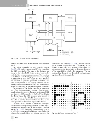
operate the raster scan in synchronism with the video characters F and P (see Fig. 23.1-24). The dots are gen-
signal. erated by switching on the active LCD element at the
The video controller in the example system desired location. The LCD is switched by pulsing the
(Fig. 23.1-23) itself incorporates an MPU for controlling video voltage at the time relative to the row and column
the CRT-type display. The data to be displayed are of the active LCD at which a dot is to appear. The res-
stored in the video RAM via the system buses under olution of the display is one dot, which is often termed
control of the instrumentation computer. The operation a picture element (i.e., a pixel).
of the MPU is controlled by programs stored in a display
ROM (DROM). This ROM might also store data that
are required to generate particular characters. The
various components of the display controller are in-
ternally connected by means of data and address buses
similar to those used in the instrumentation computer.
The operation of the display controller is under con-
trol of the instrumentation computer. This computer
transfers data that are to be displayed to the video RAM,
and signals the CRTcontroller via the UART link. During
the display time, the MPU operates under control of
programs stored in the DROM. These programs cause
the MPU to transfer data from the video RAM to the
video generator in the correct sequence for display.
The details of the transfer of data to the video gen-
erator and the corresponding generation of video signals
vary from system to system. In the hypothetical system
seen in Fig. 23.1-22, the display is assumed to be an array
of LCD elements arranged in 240 rows vertically by 480
columns horizontally. Here, the display generates the Fig. 23.1-24 Display of characters F and P.
802