
Page 789 - Automotive Engineering Powertrain Chassis System and Vehicle Body
P. 789
CHAP TER 2 3. 1 Automotive instrumentation and telematics
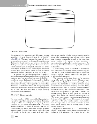
Fig. 23.1-21 Raster pattern.
flowing through the respective coils. The raster pattern the current rapidly (ideally instantaneously) switches
traced by the beam is illustrated on the face of the CRT to the value corresponding to the left edge, and the scan-
in Fig. 23.1-21. The raster begins at the upper left of the ning continues periodically. A graph of the beam hori-
screen and sweeps rapidly to the right. During this scan, zontal position with respect to time resembles a
the intensity of each electron gun varies in proportion to sawtooth pattern and is called a sawtooth waveform. The
the brightness (of each color) to be illuminated at each frequency of this horizontal sweep signal (U.S. standard)
picture element (known as a pixel). The next line in the is 15,750 Hz.
raster begins at the left of the screen slightly below the A similar sweep circuit causes the CRT beam to de-
previous line. The standard raster for U.S. television flect vertical so that the entire screen is covered in 1 sec.
30
consists of 525 lines completed 30 times per second. In actual fact, even number horizontal traces are scanned
1
1
The scanning motion is done in synchronism with the in 60 sec and odd number lines in the next 60 sec in
source of information being displayed. At the end of each a process called interlacing.
horizontal scan line, a synchronizing pulse (called hori- The horizontal and vertical signals can be generated
zontal sync) causes the beam to deflect rapidly to the left using either analog or digital circuits, although modern
and then to begin scanning at a constant rate to the right. CRTcircuits are digital. One conceptually simple way to
A similar synchronizing pulse is generated at a time when generate the horizontal and vertical sawtooth sweep
the beam is at the bottom of the CRT. This pulse (called waveforms uses a constant-frequency oscillator driving
vertical sync) causes the beam to deflect rapidly to the the trickle count input of a counter circuitry and D/A
top of the CRT face and then to begin scanning converter circuitry. Each cycle of the oscillator causes
downward at a uniform speed. the counter to increment by one. In CRT systems, the
counter output drives an A/D converter, creating an
23.1.12.1 Scan circuits output signal having the required sawtooth waveform.
The lowest count yields a current corresponding to the
The raster scan for a CRT is accomplished by varying the left edge of the CRT screen. The counter is automati-
current through the horizontal and vertical deflection cally reset to this value once the electron beam position
coils (i.e., HDCs and VDCs). At the beginning of each is at the right edge of the screen (controlled by hori-
horizontal line, the current through the HDC is such that zontal synch pulses). Similar circuitry exists to drive
the electron beam is at the left edge of the CRT face (as vertical deflection.
viewed from the front). Then this current increases Deflection of a solid-state (e.g., LCD) equivalent of
with time such that the beam sweeps uniformly from the CRT is dependent on the wiring arrangement of the
left to right. At the time the beam is at the right edge, individual LCD elements. One scheme for achieving
800