
Page 782 - Automotive Engineering Powertrain Chassis System and Vehicle Body
P. 782
Automotive instrumentation and telematics C HAPTER 23.1
Fig. 23.1-12 Coolant temperature sensor.
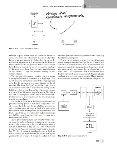
message display rather than an indicated numerical assumed pressure sensor is hypothetical and used only
value. Whenever the oil pressure is outside allowable for illustrative purposes.
limits, a warning message is displayed to the driver. In During the measurement time slot, the oil pressure
the case of oil pressure, it is important for the driver to sensor voltage is sampled through the MUX switch and
know whenever the oil pressure falls below a lower converted to a binary number in the A/D converter. The
limit. It is also possible for the oil pressure to go above computer reads this binary number and compares it with
an allowable upper limit; however, many manufacturers the binary number in memory for the allowed oil pres-
do not include a high oil pressure warning in the sure limits. The oil pressure limit is determined from
instrumentation. load or crankshaft speed measurements that are already
The simplest oil pressure warning system involves available in the engine control system. These measure-
a spring-loaded switch connected to a diaphragm. The ment data can be sent to the instrument subsystem via
switch assembly is mounted in one of the oil passageways
such that the diaphragm is exposed directly to the oil
pressure. The force developed on the diaphragm by the
oil pressure is sufficient to overcome the spring and to
hold the switch open as long as the oil pressure exceeds
the lower limit. Whenever the oil pressure falls below
this limit the spring force is sufficient to close the switch.
Switch closure is used to switch on the low oil pressure
warning message lamp.
One of the deficiencies of this simple switch-based oil
pressure warning system is that it has a single fixed low
oil pressure limit. In fact, the threshold oil pressure for
safe operation varies with engine load. Whereas a rela-
tively low oil pressure can protect bearing surfaces at low
loads (e.g., at idle), a proportionately higher oil pressure
threshold is required with increasing load (i.e., increasing
horsepower and RPM).
An oil pressure instrument that operates with a load-
or speed-dependent threshold requires an oil pressure
sensor rather than a switch. Such an oil pressure warning
system is illustrated in Fig. 23.1-13. This system uses
a variable-resistance oil pressure sensor such as seen in
Fig. 23.1-14. A voltage is developed across a fixed re-
sistance connected in series with the sensor that is pro-
portional to oil pressure. It should be noted that this Fig. 23.1-13 Oil pressure measurement.
793